Gas welding processes are a group of welding processes in which weld is made by melting the base metals with a flame obtained by combination of fuel gas (such as acetylene, propane, butane or natural gas) and oxygen to produce a heat, having sufficient energy to melt the base metals.
Fuel gases are burned with oxygen rather than air because the large nitrogen component of air, which contributes nothing to the combustion, results in a low-temperature flame that is below the fusion temperature of most metals. The type of fuel gas to be used is determined by the desired flame temperature. The most commonly used fuel gas in welding is acetylene and, hence, the process of gas welding is known as oxy-acetylene welding.
It should be noted here that all the fuel gases used in welding are hydrocarbons consisting of carbon and hydrogen. When they are burned with pure oxygen, they produce carbon dioxide and water, which can damage the metals being welded, like titanium is harmed by these elements. Therefore, we should be certain that the metals being welded by using gas welding are not reactive to the resulting compounds.
Advantages of gas welding
1. Because oxy acetylene gas welding requires minimal equipment, it is portable, inexpensive and suitable for manual methods.
2. Weld bead size and shape and weld puddle viscosity are also controlled in the welding process because the filler metal is added independently of the welding heat source.
3. The gas welding setup can be quickly converted to metal cutting.
4. Excellent control of temperature of weld zone. Ideal for thin metals, small pipe, poor fit-up, smoothing or repairing rough arc welds.
5. Used as source of heat for bending, forming, straightening, hardening.
Disadvantages of gas welding
1. Gas welding involves manual operation.
2. Gas welding process is slow.
3. Gas welding requires proper training of worker.
Oxyacetylene gas welding process burns acetylene gas in oxygen stream creating a very high flame temperature of approximately 33000C. The basic technique involves melting the edges of a joint so they can be fused together. A filler rod may also be used to supply molten metal to the interface, and may have flux coating to retard oxidation by generating a gaseous shield around the weld area and dissolving surface oxides.
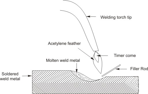
Figure 1: Schematic view of oxy-acetylene gas welding process
The oxygen is supplied from steel cylinders and the acetylene either from cylinders or from an acetylene generator. With cylinder gas, the pressure is reduced to 0.06 N/mm2 or under, according to the work, by means of a pressure-reducing valve and the acetylene is passed to the torch where it is mixed with oxygen in approximately equal proportions, and finally passed into the tip to be ignited.
Chemical reaction resulting from the combustion of acetylene with oxygen is an exothermic reaction in which equal volumes of acetylene and oxygen react to produce carbon monoxide, and hydrogen as products of the first stage of combustion. Theoretically, equal volumes of oxygen and acetylene are supplied to the torch. The reaction is as follows:
Stage 1
C2H2 + O2 = 2CO + H2
CO + H2 + O2 = CO2 + H2O
In Stage 2, the carbon monoxide burns and forms carbon dioxide, while the hydrogen which is formed in Stage 1, combines with oxygen to form water. The combustion is therefore complete and carbon dioxide and water (turned to steam) are the chief products of combustion. This produces a flame temperature of approximately 3200oC.
The oxy-acetylene flame has three sections: the inner cone, the middle acetylene feather, and the outer flame envelope. The ratio of the length between the inner cone and the middle acetylene feather should be controlled by adjusting the gases. The temperature of the oxyacetylene flame is not uniform throughout its length of the flame. The temperature is highest just beyond the end of the inner cone and decreases gradually toward the end of the flame. It is so high up to 3316oC.
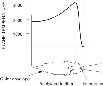
Figure 2: Temperature distribution along the length of the flame
The neutral flame is obtained when equal proportions of acetylene and oxygen are used and combustion is complete by consuming all the carbon supplied by the acetylene and the maximum heat given out. In neutral flame, the flame contracts and the white rounded shape cone become clearly visible. This type of flame is extensively used by the welder. In neutral flame, the temperature at the inner cone tip is approximately 3232oC, while at the end of the outer envelope the temperature drops to approximately 1260oC. When steel is welded with this flame, the puddle of molten metal is quiet and clear, and the metal flows without boiling, foaming, or sparking.
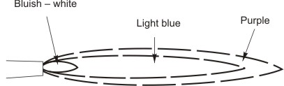
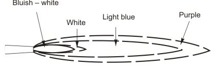
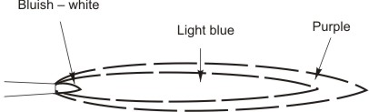
Figure 3: Temperature distribution along the length of the flame
2.3.2 Carburizing flame (Reducing flame)
The carbonizing flame is obtained with excess of acetylene and showing two cones of flame in addition to an outer envelope. Since it contains excess of acetylene its flame temperature is lower, and the available carbon is not burnt completely because of less oxygen. This flame should not be used for welding steel as unconsumed carbon may be introduced into the weld and produce a hard & brittle deposit. The carburizing flame is best used for welding high carbon steels, for hard surfacing, and for welding non-ferrous alloys, such as Monel. It has a temperature of approximately 3149oC at the inner cone tips.
2.3.3 Oxidizing flame
Oxidizing flame consists of excess of oxygen. The inner cone becomes shorter and sharper; the flame will turn a deeper purple colour and emit a characteristic slight "hiss". The molten metal will be less fluid during welding and excessive sparking will occur. Oxidizing flame is used to braze steel and cast iron. A stronger oxidizing flame is used for fusion welding brass and bronze. The temperature of this flame is approximately 3482oC at the inner cone tip.
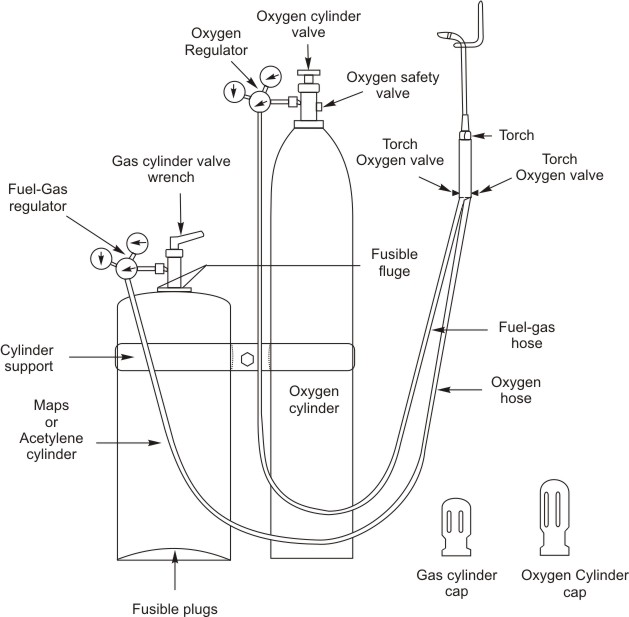
Figure 4: Schematic view of gas welding setup
It is made of steel and volume of oxygen contained in the cylinder is approximately proportional to the pressure; hence for every 10 litres of oxygen used, the pressure drops about 0.02 N/mm2. This enables us to tell how much oxygen remains in a cylinder. The oxygen cylinder is provided with a valve threaded right hand and is painted black. Oxygen cylinders and apparatus should not be handled with oily hands or oily gloves. Oil and grease in the presence of oxygen may spontaneously ignite and burn violently or explode.
2.4.2 Acetylene cylinder
Acetylene cylinder should be used in the up right position so acetone may not be drawn out of the tank. The valve has a screw tap fitted and is screwed left hand. The cylinder is painted maroon. Open the cylinder valve 1 to 1 ½ turns, leaving the valve wrench on the valve in the event it has to be shut off quickly. Acetylene should never be used at a pressure that exceeds 103.4 kPa. In order to decrease the size of the open spaces in the cylinder, acetylene cylinders are filled with porous materials such as balsa wood.
2.4.3 Pressure Regulator
The regulator maintains a steady working pressure as the cylinder pressure drops from use. On turning the knob or screw in or out causes a spring in the regulator to operate the diaphragm which opens or closes a valve in the regulator. This in turn regulates the outlet pressure and flow. By turning the adjusting knob in, there will be increase the flow and pressure; adjusting knob out, there will be decrease in the flow and pressure. Most regulators have two gauges. One shows the inlet pressure from the cylinder (the high pressure gauge) and the other (low pressure gauge) shows the working pressure being supplied from the regulator.
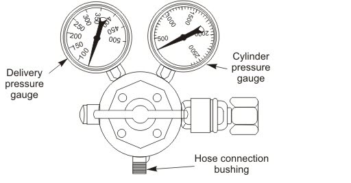
Figure 5: Pressure Regulators
The cylinder regulators and torch are usually connected together by double line rubber hoses. The oxygen line is green and fuel gas line red. Hoses are built to withstand high internal the regulators and the torch pressures. They are strong, nonporous, light, and flexible to permit easy manipulation of the torch.
2.4.5 Check Valve
Check valves are installed between the hoses and torch prevent back flow of gases as they close if a reverse flow starts. For combustion to occur, fuel and oxygen have to mix. This should only happen in the torch mixer or the torch tip. Check valves should be used with all torches.
2.4.6 Flash Back Arrestor
A flashback, which is a rapid high pressure flame in the hose can occur if there are no check valves or the check valves fail to operate due to improper installation. Arrestors are safety devices on the outlet of the oxygen and fuel gas regulators. A highly sensitive cut off mechanism operates at the slightest back pressure, whether the pressure wave is slow or sudden.
2.4.7 Torch
The oxy-acetylene welding torch mixes oxygen and acetylene gas in the proper proportions and controls the amount of the mixture burned at the welding tip. Torches have two needle valves: one for adjusting the oxygen flow and the other for adjusting the fuel (acetylene) gas flow. Other basic parts include a handle (body), two tubes (one for oxygen and another for fuel gas), a mixing head, and a tip. Two general types of welding torches are used: Low pressure & Medium pressure.
Low pressure torch is also known as an injector torch. The fuel-gas pressure is 6.895 kPa or less. A jet of relatively high pressure oxygen produces the suction necessary to draw the acetylene gas into the mixing head. Any change in oxygen flow will produce relative change in acetylene flow so that the proportion of the two gases remains constant. This is accomplished by designing the mixer in the torch to operate on the injector principle.
Medium pressure torches are often called balanced-pressure or equal-pressure torches because the fuel gas and the oxygen pressure are kept equal. Operating pressures vary, depending on the type of tip used. The pressure ranges from 6.895 to 103.4 kPa. This torch has certain advantages over the low pressure type, i.e., it can be more readily adjusted, and since equal pressures are used for each gas, the torch is less susceptible to flashbacks.
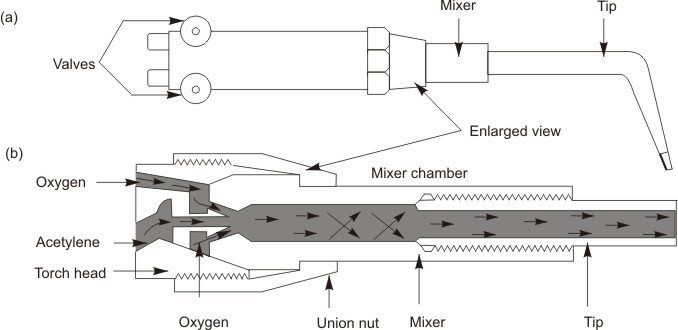
Figure 6: Temperature distribution along the length of the flame
Welding torch tips are made from a special copper alloy. The welding torch tip is mounted on the end of the torch handle and through it the oxygen and fuel gas mixture feed the flame. Welding tips have one hole. Many factors determine the tip size to use, but mainly the thickness of the metal to be welded determines the tip size to be used.
The welding rod is melted into the welded joint, plays an important part in the quality of the finished weld. Good welding rods are designed to permit free flowing metal which will unite readily with the base metal to produce sound, clean welds of the correct composition.
Flux serves as a protection for the molten metal against atmospheric oxidation. The melting point of a flux must be lower than that of the metal or the oxides formed. In cast iron welding, a slag forms on the surface of the puddle. The flux serves to break this up. Equal parts of a carbonate of soda and bicarbonate of soda make a good compound for this purpose. Nonferrous metals usually require a flux. Borax which has been melted and powdered is often used as a flux with copper alloys. A good flux is required with aluminum, because there is a tendency for the heavy slag formed to mix with the melted aluminum and weaken the weld. For sheet aluminum welding, it is customary to dissolve the flux in water and apply it to the rod.
To ignite the flame at the tip of the welding torch, hold it so as to direct the flame away from the operator, gas cylinders, hose, or any flammable material. Open the acetylene torch valve ¼ turn and ignite the gas in front of the tip. Continue to open the acetylene valve slowly until the flame burns clean. Slowly open the oxygen valve. The flame changes to a bluish white and forms a bright inner cone surrounded by an outer flame. The inner cone develops the high temperature required for welding. The inner cone of the burning mixture of gases coming out from the tip is called the working flare. The closer the end of the inner cone is to the surface of the metal being welded, the more effective is the heat transfer from flame to metal.
The flame can be made soft or harsh by varying the gas flow. Too low a gas flow for a given tip size will result in a soft, ineffective flame sensitive to backfiring. Too high a gas flow will result in a harsh, high velocity flame that is hard to handle and will blow the molten metal from the puddle.
(1) Contaminants present in the form dirt, oil, and oxides of must be removed along the joint and sides of the base metal.
(2) The root opening for a given thickness of metal should be large enough to permit full penetration.
(3) The thickness of the base metal at the joint determines the type of edge preparation for welding. Edges with square faces can be butted together and welded. This type of joint is limited to material under 4.8 mm in thickness. For thicknesses of 4.8 to 6.4 mm, a slight root opening or groove is necessary for complete penetration.
(4) Joint edges of 6.4 mm and thicker should be beveled because beveled edges at the joint provide a groove for better penetration and fusion at the sides.
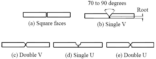
Figure 7: Edge preparations for butt joints
1. Gas and oxygen flow rates (flame adjustment and torch manipulation).
2. Distance from surface.
3. Edge preparation, spacing and alignment of the parts.
4. Speed.
5. Material types.
6. Temperature control (before, during, and after the welding process).
7. Size of the torch tip.
8. Size and type of the filler rod.
| Lecture 1 | Lecture 3 |