After studying this unit, you should be able to understand:
i. introduction to welding,
ii. different types of welding processes and their classification,
iii. welding tools and equipment, and
iv. welding defects and their remedies.
Welding is one of the most convenient and rapid methods available for joining metals. In general welding can be defined in its broadest sense as the formation of a metallic bond by heating metals to their melting temperature. More and more products are being fabricated using welding due to its advantages, i.e. ease, economy, strength and freedom in design. Applications of welding processes range from fabrication of simple steel brackets to nuclear reactors. The number one enemy to welding is oxidation, and consequently, many welding processes are carried over in a controlled environment or shielded by an inert atmosphere.
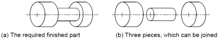
Figure 1: Typical component that can be manufactured by joining
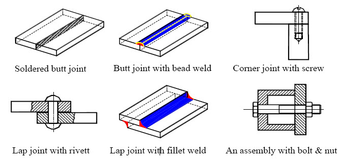
Figure 2: Examples of joints that can be made by different joining processes
Consider two ice cubes outside the refrigerator, the outer surfaces of the cubes under the heat of the day will begin to melt. Now place the two wet cubes one on top of the other back in the refrigerator and within a short time you will observe that the two cubes are joined (welded) together to form one block of ice. The addition of heat has melted portion of the two cubes to be joined and later they both cool down to form one cube, the melted section becoming an integral part of the bond.
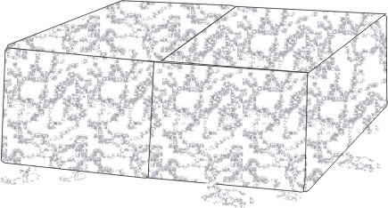
Figure 3: Welding of two ice cubes
Welding is defined as "a joining process that produces coalescence of materials by heating them to the welding temperature, with or without the application of pressure or by the application of pressure alone, and with or without the use of filler metal".
(Coalescence means fusion or growing together of the grain structure of the materials being welded.)
Weld is defined as "a localized coalescence of metals or nonmetals produced either by heating the materials to the required welding temperatures, with or without the application of pressure, or by the application of pressure with or without the use of filler materials".
Before we start discussing the welding process, few of the terminologies used in the process of welding are explained.
Base metal: The workpieces to be joined are known as base metals.
Weld bead: It is the material, which is deposited by the process of welding. This appears as a separate material from the base metal in the form of a bead. This also referred to as bead.
Puddle: It is the portion of the base metals at the joint, which is melted by the heat of welding.
Weld pass: It is the movement of welding torch from one end of the joint to the other end, which results in bead.
Tack weld: A temporary weld done at the ends of the workpieces, during welding to hold the workpieces together.
1.1.1 Advantages of welding process [1]. It is faster and economical in comparison to other joining process i.e. riveting, fastening etc. As it does not require overlapping materials, it eliminates excess weight caused by other fastening means.
[2]. Similar and dissimilar metals can be joined more easily and strongly.
[3]. Joint obtained by welding is a permanent one and strong one.
[4]. Equipment is not very costly.
[5]. Process is portable and can be taken to site easily.
[6]. Process can be automatic and mechanized.
[7]. It is a leak proof process.
1.1.2 Disadvantages of welding process:
[1]. The U-V (Ultra Violet) rays emitted during the arc welding process are extremely harmful for human eyes.
[2]. The fumes and gases of welding process are harmful to the humans.
[3]. Thermal stresses induced and distortion of the jobs are unavoidable.
[4]. For a good weld, the operator must be skilled one.
[5]. Designs must account for the heating produced by welding.
1.1.3 Applications of welding process
Due to its number of advantages the welding process is widely used in every phase of metal industry. Some of the prominent applications are:
[1]. Building and bridge construction
[2]. Pipelines
[3]. Aircraft manufacturing
[4]. Ship fabrication
[5]. Automobiles
[6]. Oil industry's rigs, pipe lines etc.
[7]. Military war equipment.
[8]. Many other branches of industry.
It is defined as "The capacity of metal to be welded under fabricating restrictions imposed, into a specific designed structure and to perform satisfactorily in the intended service". We can say in short that weldability is the ability of a metal to weld satisfactorily.
Classification of welding process is done on the basis of the equipment used and the method of heat application.
1.3.1 Autogeneous welding: Consists of those processes in which similar metals are joined with the help of filler rod of same metal.
i.e. M.S. to M.S. and C.I. to C.I.
1.3.2 Heterogeneous welding: Consists of those processes in which dissimilar metals are joined, .i.e. Cu with Al
1.3.3 Pressure welding: Involves heating of the base metals, which are to be joined up to their plastic state, and joining them by applying pressure. No filler material is used in this type of welding. Forge Welding and Flash welding are the examples of it.
1.3.4 Non-pressure welding: All fusion welding processes are non-pressure welding process as no pressure is applied during joining of the workpieces by welding.
1.3.5 Solid state welding: The main characteristic of solid state welding is that no liquid phase is present in the process. Solid state welding joins parts by applying heat and pressure. In this two clean surfaces are brought together under the influence of heat and pressure to initiate bonding between them. Relative motion (rubbing) between two surfaces generates heat through friction and breaks up oxide film allowing the pure metal to interact. The temperature is usually below the melting point of the materials joined. Forge, resistance, ultrasonic, diffusion, inertia and explosive welding are examples of solid state welding.
1.3.6 Fusion welding: Fusion welding involves heating of the base metals that are to be joined to the temperatures above their melting point. It involves the use of additional filler material. Work pieces are joined without the application of pressure. Types of fusion process are arc welding, metal arc, carbon arc, inert gas arc, atomic hydrogen arc, submerged arc welding.
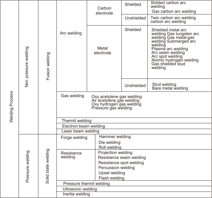
Figure 4: Generalized classification of welding process
It is important that one should become familiar with weld and the terms used to describe a weld.
1.4.1 Filler penetration or fusion zone: It is the region of the base metal that is actually melted. The depth of fusion is the distance that fusion extends into the base metal.
1.4.2 Leg of a fillet weld: The leg is the portion of the weld from the root of the joint to the toe of the weld. There are two legs in a fillet weld.
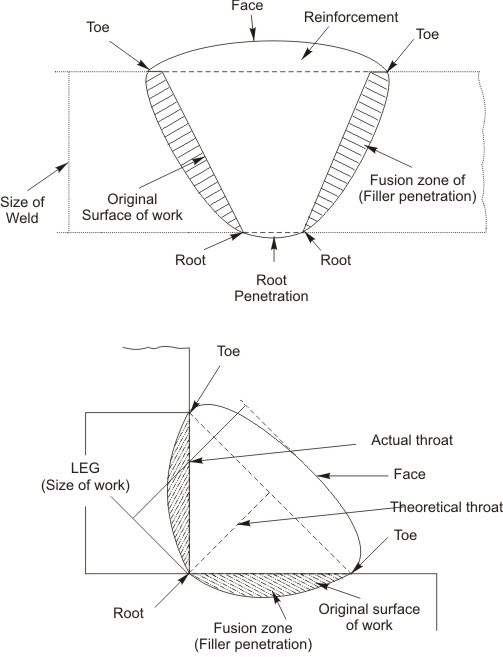
Figure 5: Features of weld
1.4.3 Root of the weld: This is the point at which the bottom of the weld intersects the base metal surface, as shown in the cross section of weld.
1.4.4 Throat of a fillet weld: The throat is the distance from the root to a point on the face of the weld along a line perpendicular to the face of the weld.
1.4.5 Face of the weld: This is exposed surface of a weld, made by an arc or gas welding process on the side from which the welding was made.
1.4.6 Toe of the weld: This is the junction between the face of the weld and the base metal.
1.4.7 Reinforcement of the weld: This is the weld metal on the face of a groove weld in excess of the metal necessary for the specified weld size.
1.4.8 Heat Affected Zone (HAZ): Heat affected zone (HAZ) is the portion of the base metal which has not been melted but has been rapidly heated and cooled by the passage of the welding arc. The metal between the HAZ is weld metal, a mixture of deposited metal and some of the parent metal which has been melted. In HAZ structural or mechanical properties of the metal have been altered by the welding heat.
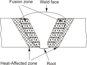
Figure 6: Schematic view of heat affected zone
1.4.9 Size of the weld: The size of welds is specified as follows:
For butt welds - throat thickness
For fillet welds - Leg length or throat thickness
Joint is a junction of parts and defines the location of two or more members to be joined. The configuration of the workpieces that are to be connected determines the type of joint. Typical joints are:
1.5.1 Lap Joint: A joint between two overlapping members i.e. is made by lapping one piece of metal over another. This is one of the strongest types of joints available. Overlap the metals minimum three times the thickness of the thinnest member being joined. Lap joints are commonly used spot welding applications.
1.5.2 Butt Joint: A joint between two members lying approximately in the same plane. This joint is frequently used in plate, sheet metal, and pipe work.
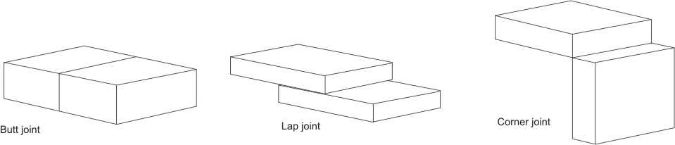
Figure 7: Types of joints
1.5.3 Corner Joint: A joint between two members located approximately at right angles to each other in the form of an angle. In cross section, the corner joint forms an L-shape.
1.5.4 Edge Joint: A joint between the edges of two or more parallel members. An edge joint should only be used for joining metals that are not subjected to heavy loads. It is more frequently used in sheet metal work.
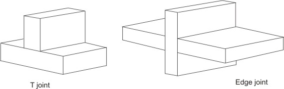
Figure 8: Types of joints
1.5.5 Tee joint: A joint between two members located approximately at right angles to each other in the form of a T. In cross section, the tee joint has the shape of the letter T.
The terms weld and joints are often confused in welding process. There are two major classes of weld, i.e. fillet and butt.
1.6.1 Butt welds: A butt weld is made between two pieces of metal usually in the same plane, the weld metal maintaining continuity between the sections.
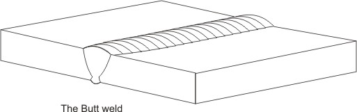
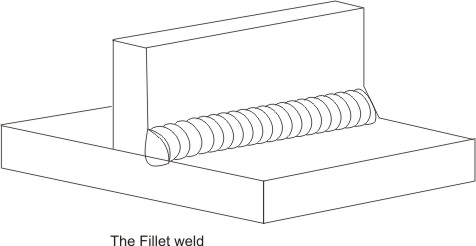
Figure 9: Types of weld
1.6.2 Fillet welds: Fillet welds are roughly triangular in cross section and between two surfaces not in the same plane and the weld metal is substantially placed alongside the work pieces being joined.
In addition there are lap welds, corner welds and edge welds, which are to some extent special variations of the fillet and butt welds.
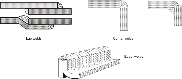
Figure 10: Types of weld
1.6.3 Edge preparations for welding
To obtain sound welds, it is desirable that weld should completely penetrate the metal thickness. The heat will not be able to melt the joint edges to their entirethickness if thick plates are to be welded. Complete penetration becomes more important in case of butt joints. Hence, to obtain complete penetration and sound welds, edge preparation is essential. Figure shows different edge preparations for butt joints.
Edges with square faces as shown in Figure(a) can be used only up to a particular thickness. Above that, proper penetration depth of the welds cannot be achieved and sound welds will not be obtained. To over come this problem, the edges cut to make single-V groove, as shown in Figure (b), or single-U groove, as shown in Figure (d). The maximum thickness for which weld penetration is possible with square faces is called root. Thus, V or U grooves are made leaving a thickness equal to root as a square butt joint. By making these grooves, the depth of penetration of welds is more and hence we can obtain sound welds. If the thickness of the material is too large, either double-V (Figure (c)) or double-U (Figure (e)) groove should be used.
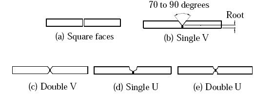
Figure 11: Edge preparations for butt joints
Welding is done in one of the four positions: (1) flat, (2) horizontal, (3) vertical, or (4) overhead.
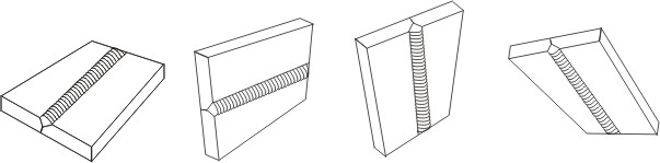
Figure 12: Positions of welding (1) flat, (2) horizontal, (3) vertical, and (4) overhead
1.8.1 Leftward welding technique (Forehand welding)
As the name implies, the weld is started at the right hand side and progresses towards the left. This position permits uniform preheating of the plate edges immediately ahead of the molten puddle. By moving the torch and the rod in opposite semicircular paths, the heat can be carefully balanced to melt the end of the rod and the side walls of the plate into a uniformly distributed molten puddle. The rod is dipped into the leading edge of the puddle so that enough filler metal is melted to produce an even weld joint. The heat which is reflected backwards from the rod keeps the metal molten and the metal is distributed evenly to both edges being welded by the motion of the tip.
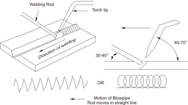
Figure 13: Schematic view of leftward welding technique
The filler rod precedes the torch and is held at an angle of 30o - 40o to the work surface. The torch is held at an angle of 60o - 70o to the work surface and is given a slight side-to-side movement to ensure side fusion as the filler rod is fed into the molten pool. The flame is pointed in the direction of welding and directed between the rod and the molten puddle. This method is used on low carbon steel sheet and plate in thicknesses up to 6.5 mm and also on cast iron and certain non-ferrous metals.
1.8.2 Rightward welding technique (Backhand welding)
The weld is started at the left hand side of the joint and progresses towards the right. In this method, the torch precedes the welding rod. The torch is held at approximately at an angle of 40o - 50o to the work surface and travels in a straight line, with the flame directed at the molten puddle. The filler rod, which is held at an angle of 30o - 40o to the work surface, follows the torch and is fed into the molten pool with a circular action. The advantages of rightward welding over the leftward technique are higher speed, less distortion and more economical use of gas and filler rod. By this technique there is greater ease of obtaining fusion at the weld root. This method is used on welding of steel plate over 5 mm thickness.
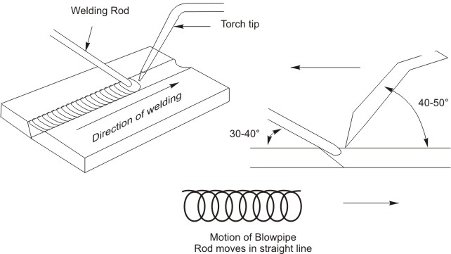
Figure 14: Schematic view of rightward welding technique
Flux is a cleaning agent material used to obstruct or prevent the formation of oxides and other undesirable substances in molten metal and on metal surfaces. Flux allows the filler metal and the base metal to be fused. Different types of fluxes are used with different types of metals; therefore, one should choose a flux formulated for a specific base metal. Select a flux based on the expected welding temperature. The ideal flux has the right fluidity at the welding temperature and thus blankets the molten metal from oxidation. Fluxes usually come in the form of a paste, powder, or liquid. Powders can be sprinkled on the base metal, or the filler rod can be heated and dipped into the powder. Liquid and paste fluxes can be applied to the filler rod and to the base metal with a brush. For shielded metal arc welding, the flux is on the electrode.
Characteristics of a good flux:
[1]. It is fluid and active at the melting point of the filler metal.
[2]. It remains stable and does not change to a vapor (ball up or blow away) rapidly within the temperature range of the welding.
[3]. It dissolves all oxides and removes them from the joint surfaces.
[4]. It does not cause a glare that makes it difficult to see the progress of welding or brazing.
[5]. It is easy to remove after the joint is welded.
[6]. It is available in an easily applied form.
Functions performed by flux:
[1]. Stabilizes the arc.
[2]. Generates shielding gases.
[3]. Controls the electrode melt rate.
[4]. Prevent oxide, nitride formation.
[5]. Adds alloying elements to the weld.
While welding two pieces of metal together, space is left between the joints. The material used to fill this space during the welding process is known as the filler metal, or material. Two types of filler metals commonly used in welding are welding rods and welding electrodes. The term welding rod refers to a form of filler metal that does not conduct an electric current during the welding process. The only purpose of a welding rod is to supply filler metal to the joint. This type of filler metal is often used for gas welding.
| Lecture 2 |