Combination Set
The combination set, as its name implies, is a tool that has several uses. The set consists of a blade (graduated rule), square head, protractor head, and center head. The grooved rule is used with each head. The groove permits the rule to be moved into position and locked.

Figure 1: Combination set
Note: While using the combination set make sure to remove burrs and chips, and wipe the head and workpiece clean. Check the sharpness of the scriber point if you are marking lines.
Blade (Rule)
The blade is designed to allow the different heads to slide along the blade and be clamped at any desired location. The groove in the blade is concave to eliminate dirt buildup and permit a free and easy slide for the heads. By removing all the heads, the blade may be used alone as a rule.
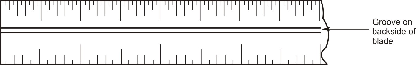
Figure 2: Blade with groove
Square Head
A combination square has a ruled blade with an angled head that slides along the blade and can be repositioned by locking nut at any desired place along the graduated, rule-type blade to suit the job. The square head is designed with a 45o and 90o edge. The square head and blade can also be used as a marking gauge to scribe lines at a 45o angle. A convenient scriber is held frictionally in the head by a small brass bushing. By extending the blade below the square or above the square, it can be used as a depth gage or height gage. Level in the angled head is used to make sure your work is true horizontal (level) or true vertical (plumb). The trick is to always use the longest level possible. The level makes it convenient to square a piece of material with a surface and at the same time will indicate if the edge or surface of the material is level. The square head can also be used as a simple level.
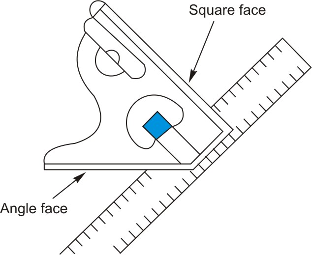
Figure 3: Square head
Using square head
1. For checking angles, rest the head on its square face to check a 90o angle and on its angled face to check 45o.
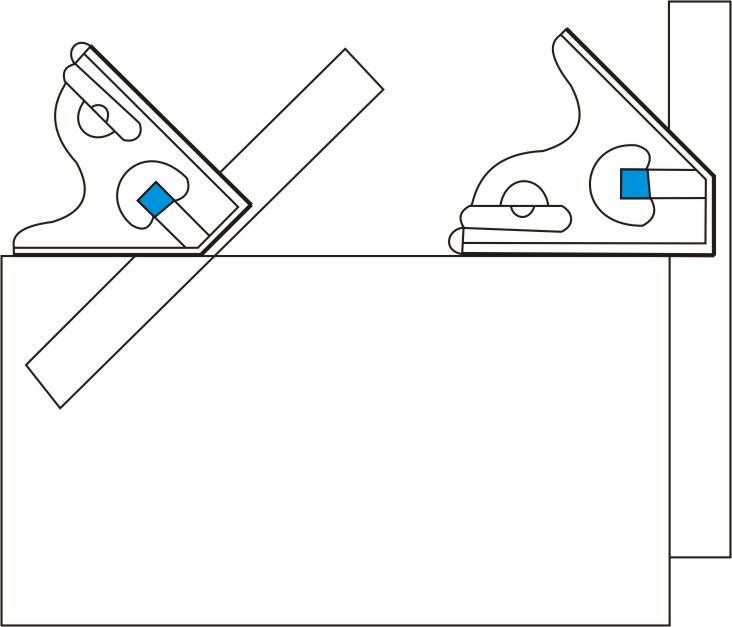
Figure 4: Use the head to check for level
2. For measuring depth, loosen the locking nut, rest the square face flat on the reference surface and push the rule into the depth. Tighten the locking nut, remove the rule and read the depth.
3. For checking horizontal surface, rest the square face of the head on the surface with blade removed and reinstall the blade and check vertical surfaces by holding the blade against the vertical member to see that it is plumb.
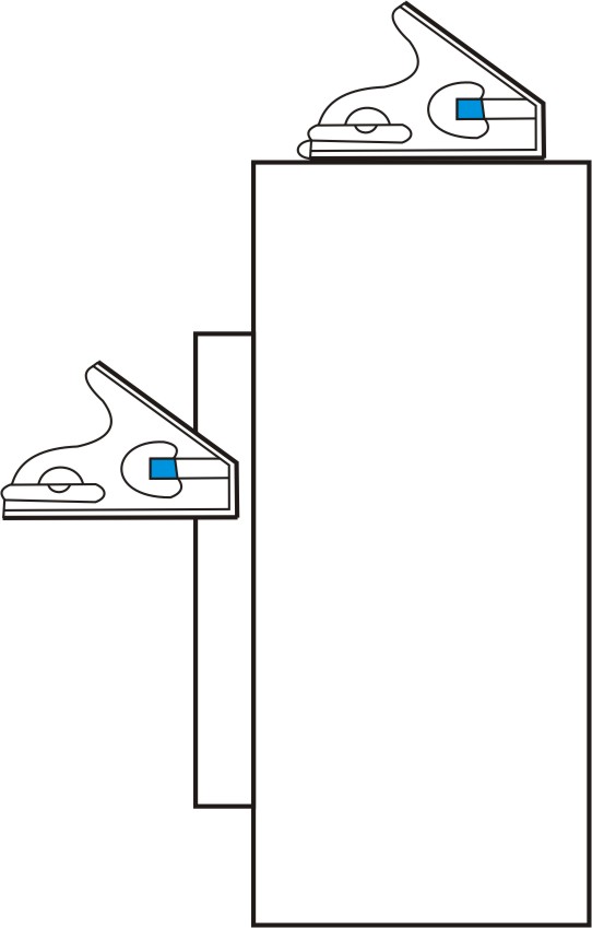
Figure 5: Checking horizontal surface
4. For laying out a line, move the blade until it extends the required distance from the head. This measurement is read on the scale of the blade. Lock the blade and the square head using locking nut and position the head firmly against the reference surface. Scribe the required line.
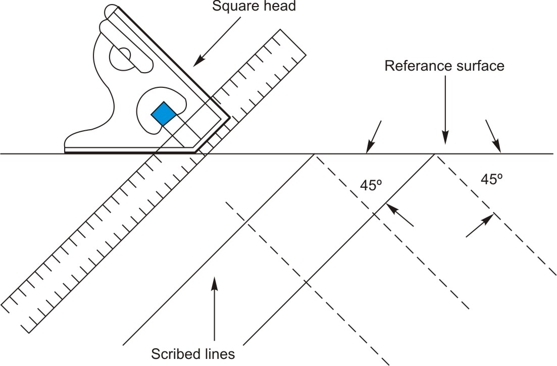
Figure 6: Scribing lines at 45o using square head
5. For measuring length hold the head firmly against the reference surface. Move the blade until it exactly splits the measured point. Read the dimension on the blade of the square head.
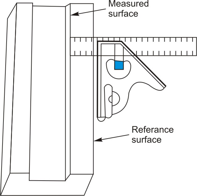
Figure 7: Measuring surface using square head
Protractor Head
The protractor head is equipped with a revolving turret that is graduated in degrees from 0 to 180 or to 90 in either direction. It is used to measure or lay out angles to an accuracy of 1°. The base of the protractor head is held against the reference surface. The blade is held to the turret. The revolving turret is turned until the included angle of the blade and protractor head coincides with the angle to be measured.
Using protractor head for measuring and marking an angle
1. Loosen the revolving turret locking nut to allow the turret to be rotated when a slight force is applied.
2. Press the flat face of the protractor head against the reference surface.
3. Position the protractor head so that the blade and turret may be moved to the desired angle and mark off the angle.
4. For measuring an angle bring the blade down gently to the work piece and adjust it. The desired angle is reached when there is no light showing between the measured surface of the work and the blade.
5. Tighten the locking nut. Read the graduation on the turret that coincides with the reference mark on the protractor head.

Figure 8: Using protractor head
Center Head
The center head, when inserted on the blade, is used to locate and lay out the center of cylindrical workpieces.
Using the center head
1. Place the V legs of the center head against the outer Surface of the cylindrical workpiece. Hold it in this position.
2. Scribe the centerline with a sharp scriber along the blade.
3. Turn either the round base 900 or the center head over. Hold the center head firmly against the bar.
4. Scribe the second centerline along the blade.
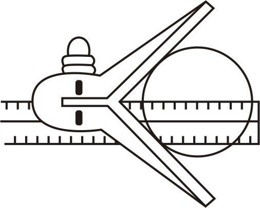
Figure 9
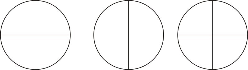
Figure 10: Laying out center on cylindrical workpiece using center head
| Tutorial 2 | Tutorial 4 |