When dies are uneconomical to make for a forming operation because of small number of parts to be made, spinning could be a solution.
Metal spinning is a term used to describe the forming of metal into seamless (jointless), axisymmetric shapes by a combination of rotational motion and force. Metal spinning typically involves the forming of axisymmetric components over a rotating mandrel using rigid tools or rollers.
Figure 1 shows examples of products made from metal spinning. The range of components include:
• Bases, baskets, basins, and bowls
• Bottoms for tanks, hoppers, and kettles
• Canopies, caps, and canisters
• Housings for blowers, fans, filters, and flywheels
• Ladles, nozzles, orifices, and tank outlets
• Pails, pans, and pontoons
• Cones, covers, and cups
• Cylinders and drums
• Funnels and horns
• Domes, hemispheres, and shells
• Rings, spun tubing, and seamless shapes
• Vents, venturis, and fan wheels

Figure 1: Various components produced by metal spinning
The equipment for metal spinning is based on lathe technology, with appropriate modifications for the components that are being formed. Typically, sheet performs flat sheet) are employed to allow relatively low forming stresses. Metal spinning can be used to cost-effectively produce single or a small number of parts out of expensive materials. In manual spinning, a circular blank of a flat sheet, or preform, is pressed against a rotating mandrel using a rigid tool. The mandrel is mounted on the lathe head stock and the live centre (tail stock) of lathe is used to hold the sheet metal in place. The spinning tool is moved either manually or hydraulically over the mandrel to form the component, as shown in Figure 2 & 3. The forming operation can be performed using several passes. As shown in figure 2 & 3. Then sheet metal is formed over it (mandrel) by the spinning operation as shown in Figure 2 & 3.Tools of different configurations can be used.
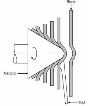

| Figure 2: Metal spinning process, showing the deformation of a metal disk over a mandrel to form a cone | Figure 3: Spinning process to form sheet metal over a revolving mandrel |
The process of shaping metals and alloys into semi-finished or finished condition by passing between rolls is known as rolling. This process involves the plastic deformation of the metal in which the thickness of the metal is reduced, while the length and width are increased. There are two types of rolling process, flat and profile (shape) rolling. In flat rolling the final shape of the product is either flat
sheet (typically thickness less than 3 mm, also called "strip") or plate (typically thickness more than 3 mm). In profile rolling the final product may be a round rod or other shaped bar, such as a structural section (rails for railway lines, girders for bridges (I-beam), channel, joist, 900 angle section, etc). Rolling is the most used metal forming process and accounts for about 90 percent of all metal
products produced by metal forming. Rolling is also classified according to the temperature of the metal rolled. If the temperature of the metal is above its recrystallization temperature, then the process is termed as hot rolling. If the temperature of the metal is below its recrystallization temperature, the process is termed as cold rolling.
Typical characteristics of rolling are:
1. Production of flat parts at high speeds
2. Production of various structural shapes
3. High capital investment
4. Low to moderate labor cost
The process of rolling consists of passing the ingot (the piece of metal to be rolled) through two rolls rotating in opposite directions at a uniform peripheral speed. The space between the rolls is adjusted to confirm to the desired
thickness of the rolled section. The rolls, thus, squeeze the ingot and as it comes out of the rolls, its thickness or cross section is reduced and its width and length are increased. The rolling process is shown in Figure 5.1.

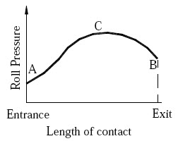
| Figure 5.1 Rolling process and deformation of grains in rolling | Figure 5.2 Pressure variation in rolling |
The structural changes that occur in the material during the rolling process are shown in Figure 5.1. Because of squeezing, the grains are elongated in the direction of rolling and the velocity of material at exit is higher than that at the entry. After crossing the stress-zone, grains start refining in the case of hot rolling. In cold rolling, grains retain the shape acquired by them during rolling.
The rolls are in contact with the metal for a distance AB, as shown in Figure 5.1. The angle AOB subtended at the center of the roll by the arc AB is known as angle of contact or the angle of bite. It is the friction between the surfaces of the metal and the rolls, which provides the required grip of the rolls over the metal piece to draw the latter through them. The greater is the coefficient of friction more is the possible reduction. However, energy is dissipated in overcoming friction, so increasing friction means increasing forces and more power consumption. Furthermore, high friction could damage the surface of the rolled product. We therefore have to make a compromise. For obtaining low coefficients of friction, effective lubricants are used.
The pressure distribution in rolling process is shown in Figure 5.2. The pressure distribution is not uniform throughout, but varies as shown. It is seen from the figure that it is minimum at both ends and maximum at a point C somewhere in between A-B. From point A to point C the metal moves slower than the roll and from C to B, the metal moves faster than the roll.
Note: It can be argued at this point that even by simply stretching the material, we can reduce the thickness of the bar then why do we require rolling process? At the outset, the question seems to be meaningful, but a moment's thought will answer the question. Simply stretching the material will not cause uniform deformation of the material, also, when the material is stretched beyond its yield point, it may even cause the fracture of the material.
Roll-work contact length is reduced with a lower roll radius, and this leads to lower forces, torque, and power. The four-high rolling mill uses two smaller diameter rolls to contact the work and two backing rolls behind them. Another roll configuration that allows smaller working rolls against the work is the cluster rolling mill.
Rolling is often the first process that is used to convert material into a finished wrought product. Thick starting stock (ingot) can be rolled into blooms, billets, or slabs or these shapes can be obtained directly from continuous casting Ingot. It is the initial product obtained by the casting of molten metal. It may be of circular, square or any other convenient cross-section.
Bloom: It is obtained by hot rolling of an ingot. It is the product of the first rolling down of the ingot. It is usually of square cross section with a cross-section area above 225 cm2.
Billet: The minimum cross sectional area of a billet is about 4 cm by 4 cm. However, in non-ferrous metallurgical terminology, a billet is any ingot which has been subjected to hot working by rolling, forging etc. or the term refers to a casting which is suitable for hot working.
Slab: A slab refers to a hot rolled ingot with a cross sectional area greater than 100 cm2 and with a width at least twice the thickness.
Plate and Sheet: These are intermediate products obtained by rolling. The difference between a plate and a sheet is determined by the thickness of the product. In general, plate has a thickness greater than 6 mm and sheet has a thickness less than 6 mm.
Sheet and Strip: These are rolled products with a thickness less than 6 mm. Strip refers to the rolled product with a width less than 300 mm, while sheet refers to the product of width above 300 mm.
Rolling of blooms, slabs, billets, and plates is usually done at temperatures above the recrystallization temperature (hot rolling). Sheet and strip often are rolled cold in order to maintain close thickness tolerances.

Figure 5.3: Flow chart for various flat rolling and shape rolling processes. White hot steel ingots
(continuous cast products) are passed through rolls which form the plastic steel into slab,
billet, bloom and semi-finished steel shapes. (Picture courtesy: Degarmo's Manufacturing Process)
| Semi-finished products | Bloom is the product of first breakdown of ingot (cross sectional area > 225 cm2). |
|---|---|
| Billet is the product obtained from a further reduction by hot rolling (cross sectional area > 4x4 cm2). | |
| Slab is the hot rolled ingot (cross sectional area > 100 cm2 and with a width = 2 x thickness). | |
| Further rolling steps | |
| Mill flat products | Plate is the product with a thickness > 6 mm. |
| Sheet is the product with a thickness < 6 mm and width > 300 mm. | |
| Strip is the product with a thickness < 6 mm and width < 300 mm. |
Table 1: Flat rolling products at a glance
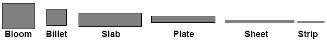
Figure 5.4: Flat Rolling Products
The distinctive mark of hot rolling is not a crystallized structure, but the simultaneous occurrence of dislocation propagation and softening processes, with or without recrystallization during rolling. The dominant mechanism depends
on temperature and grain size. In general, the recrystallized structure becomes finer with lower deformation temperature and faster cooling rates and material of superior properties are obtained by controlling the finishing temperature.
Hot rolling offers several advantages:
1) Flow stresses are low, hence forces and power requirements are relatively low, and even very large workpieces can be deformed with equipment of reasonable size.
2) Ductility is high; hence large deformations can be taken (in excess of 99% reduction).
3) Complex part shapes can be generated.
Cold rolling, in the everyday sense, means rolling at room temperature, although the work of deformation can raise temperatures to 100-200oC. Cold rolling usually follows hot rolling. A material subjected to cold rolling strain hardness
considerably. Dislocation density increases, and when a tension test is performed on this strain-hardened material, a higher stress will be needed to initiate and maintain plastic deformation; thus, the yield stress increases.
However, the ductility of the material - as expressed by total elongation and reduction of area - drops because of the higher initial dislocation density. Similarly, strength coefficient rises and strain-hardening exponent drops. Crystals (grains) become elongated in the direction of major deformation.
Cold rolling has several advantages:
1) In the absence of cooling and oxidation, tighter tolerances and better surface finish can be obtained.
2) Thinner walls are possible.
3) The final properties of the workpiece can be closely controlled and, if desired, the high strength obtained during cold rolling can be retained or, if high ductility is needed, grain size can be controlled before annealing.
4) Lubrication is, in general, easier.
A rolling mill basically consists of
• rolls
• bearings
• a housing for containing these parts
• a drive (motor) for applying power to the rolls and controlling the speed
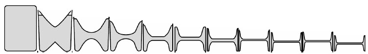
Figure 5.5: Typical roll-pass sequences used in producing structural I-Beam shape

Figure 5.6: Typical roll-pass sequences used in producing structural 900 angle shape
The arrangement of rolls at a rolling station is called a rolling mill. Rolling mills are commonly of the following types:
1. Two high, pull over
2. Two high, reversing
3. Three high
4. Four high
5. Continuous mills
6. Planetary rolling mill
7. Universal rolling mill
Figure shows different types of rolling mills and their characteristics are described below.

Figure 5.7: Different types of rolling mills
5.4.1 Two-high Rolling Mills: The name implies, it consists of two rolls between which the sheet or bar to be rolled is placed, as shown in Figure 5.7(a). The rolls rotate in one direction and rolling process is done in one direction only. The workpiece passes through the rolls and is taken over the rolls and returned to the original position for re-rolling and the process is repeated.
5.4.2 Two-high Reversing Mills: If the direction of rotation of rolls can be reversed alternately, then it is called two high reversing mill. This is shown in Figure 5.7 (b). Here the rolling is done in both directions, alternately. That is, the workpiece travels through the rolls in both the directions.
5.4.3 Three-high Rolling Mill: Three-high rolling mill is shown in Figure. In this top and bottom rolls are power driven where as middle roll rotates only by friction. In this, first stage rolling is done with one pair of rolls and same material is rolled again (second stage of rolling) through the other pair of rolls, simultaneously.
5.4.4 Four-high Rolling Mill: This is as shown in Figure. This consists of two small diameter-working rolls and two large diameter back-up rolls, placed behind the working rolls. The back-up rolls provide support and rigidity to small diameter working rolls. These types of mills require less power for rolling because of lesser frictional contact area. These are generally used for sheet rolling.
Cluster mills (sendzimir or /-mill): A cluster mill consists of two working rolls of smaller diameter which are backed by four or more back-up rolls of larger diameter [Fig. 5.7 (d)]. The sendzimir mill facility is extremely costly and is mostly used for cold rolling of thin sheets of high-strength metals.

Figure 5.8: Continuous rolling mill with four rolling mill stands
5.4.5 Continuous Rolling Mill: This is also known as tandem mill. Continuous mill is commonly used for high production. Each set of rolls is called as stand or rolling mill stand. The continuous mill is shown in Figure 5.8.
Since a different reduction takes place at each stand, the strip will be moving at different velocities at each stage in the mill. Thus, the rolls at stand 2 should run at exit velocity of material at stand 1 and rolls at stand 3 should run at exit velocity of material at stand 2 and so on. The speed of each set of rolls must be synchronized so that each successive stand takes the strip at a speed equal to the delivery speed of the preceding stand. The un-coiler and the windup reel accomplish the functions of feeding the stock to the rolls and coiling up the final product.
5.4.6 Planetary Rolling Mill
Planetary rolling mill is used to reduce slabs to coiled hot rolled strips in a single pass. This mill consists of a pair of heavy backing rolls surrounded by a large number of small planetary rolls equi-spaced on its periphery. The smaller rolls revolve about the axis of the larger roll as planets revolve around the sun. The mill is shown in Figure 5.9. Each planetary roll gives an almost constant reduction to the slab as it sweeps out a circular path between the backing roll and the slab. As each pair of planetary rolls ceases to have contact with the workpiece another pair of rolls makes contact and repeats that reduction. The overall reduction is the summation of a series of small reductions by each pair of rolls in turn following each other in rapid succession. The action in the planetary mill is more like forging than rolling. It is necessary to use feed rolls to introduce the slab into the mill, and a pair of planishing rolls may be needed on the exit side to improve the surface finish. Common rolled widths are between 0.66 and 1.5 metres.

Figure 5.9: Planetary rolling mill
5.4.7 Universal rolling mill: Universal mill consists of two pairs of rolls, axes of one pair are horizontal and the axes of other pair are vertical, mounted on a common roll stand. The horizontal rolls roll the material as in a two-high rolling mill and vertical mill does the function of giving a perfect edge to the rolled product. This type of rolling mill is used for the rolling of beams; I-sections and plate products that require rolled (finished) edges etc. This type of rolling mill is shown in Figure 5.10.

Figure 5.10: Universal rolling mill
Let l1 be the initial length, b1 be the initial breadth and t1 be the initial thickness of the workpiece, respectively. Similarly, let l2, b2 and t2 represent final length, breadth and thickness of the workpiece, respectively, after rolling.
Absolute draught: Absolute draught also called as draft is defined as the difference between the initial and final thickness of metal being rolled and is expressed as
δt = t1 - t2 (1)
The maximum possible draft, is given by
δmax = μ2R (2)
where μ = coefficient of friction between roll and work, and R = Radius of roll.
Thus, the higher the friction and the larger the roll radius, the greater is the draft giving more reduction in thickness. This situation is similar to the use of large tires and rough treads on farm tractors and off-road earth-moving equipment,
permitting the equipment to travel over rough terrain without skidding. You can better understand it if you know why serrations are provided on the tyres of your vehicle. The serrations are provided on the periphery to help in providing the grip
over the road surface. If there are no serrations, tyre will tend to slip on the road. Similarly, if the surface of the roll and workpieces are smooth then, the rolls will tend to slip over the workpiece surface without appreciable deformation.
Absolute elongation: It is the difference between final and initial length of the work piece being rolled and is given by
δ1 = l2 - l1 (3)
Absolute spread: It is the difference between final and initial breadth of the work piece being rolled and is given by
δb = b2 - b1 (4)
Relative draught: It is the ratio of absolute draught to initial thickness of the workpiece expressed as percentage of the same, and is given by
 (5)
(5)
Elongation coefficient: It is the ratio of final length to initial length and is given by
 (6)
(6)
Angle of contact: It is the angle subtended at the center of the roll by the arc of contact AB (see Figure 5.3). If a is the angle of the contact, it is given by
 (7)
(7)
where D = diameter of the roll.
Coefficient of friction: Coefficient of friction between roll and the work is given by:
μ = tan α (8)
Determine the maximum possible reduction for cold rolling a 300 mm thick slab when μ = 0.09 and the roll diameter is 700 mm. What is the maximum reduction on the same mill for hot rolling when μ = 0.09?
Solution We know that
δmax = μ2R
Hence for Cold rolling
δmax = (0.09)2 x 350
= 2.835 mm
For Hot rolling
δmax = (0.5)2 x 350
= 87.5 mm
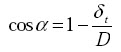
Thread rolling is essentially a cold working process in which a cylindrical workpiece, having a diameter approximately equal to the pitch diameter of the required thread, is rotated between hard dies having the negative contour of the
threads to be formed. Thread rolling is shown in Figure 5.6. In this process, the part to be threaded is rolled between two flat dies-one stationary and the other reciprocating. Reciprocating thread-rolling machines are highly versatile. Two or
three sets of flat dies each having a different thread form can be assembled in a single machine for special applications such as the rolling of different threads simultaneously, threading and knurling on the same part, rolling right and left hand threads at the same time etc.
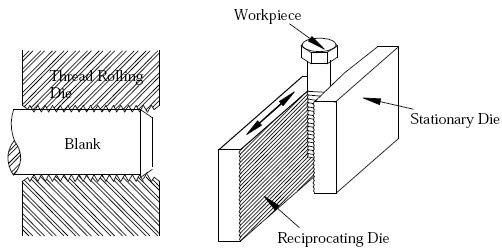
Figure 5.11: Thread rolling
Defects in hot rolled plates and sheets may occur on the surface or internally in the rolled plates and sheets. Surface defects include: scale, rust, scratches, pits, cracks, etc. These defects are caused by inclusions and
impurities present in the ingots or by other conditions related to material preparation and rolling operation. Other defects are shown in Figure 5.12.
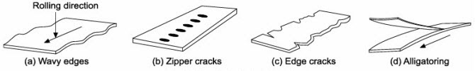
Figure 5.12: Defects in flat rolling
These are wavy edges on sheets due to roll bending: strip is thinner along edges than its centre. Other defects, namely, zipper cracks in the centre of strip and edge crack are due to poor material ductility at the rolling temperature.
Alligatoring defect is a complex phenomenon and may be because of non uniform deformation during rolling or defects already present in the cast ingot.
| Lecture 4 | Lecture 6 |