Forging equipments are classified according to their principle of operation. The two categories of forging equipment are:
(i) Forging hammers: In forging hammers, the forging force is supplied by the falling weight or ram; hence these are energy restricted machines as deformation results from dissipating the kinetic energy of the ram.
(ii) Forging presses: Mechanical forging presses are stroke restricted equipment as the length of the stroke and available loads at various positions of stroke represent their capability. Hydraulic presses are load restricted machines as their capability for carrying out forming operation is limited by the maximum load capacity of the press.
The hammer is the least expensive and most versatile type of equipment for generating load and energy to carry out a forming process. This technology is characterized by multiple impact blows between contoured dies. The hammer is an energy-restricted machine as they get their energy from the potential energy of hammer and on falling of the hammer;
this energy is converted into kinetic energy. During a working stroke, the deformation proceeds until the total kinetic energy is dissipated by plastic deformation of the material when the die faces contact each other. Therefore, it is necessary to rate the capacities of these machines in terms of energy, i.e., meter-kilograms, or meter-tons.
The practice of specifying a hammer by its ram weight is not useful for the user. Hammers are primarily used for hot forging, for coining, and to a limited extent. Hammer forging has a reputation as an excellent way to enhance the metallurgical properties of many materials.
4.1.1 Gravity drop hammers
Gravity drop hammers have a free falling ram. According to the method for raising the upper ram, the gravity hammers may be classified as, simple gravity-drop hammer, the upper ram is positively connected to a board (board-drop hammer), a belt (belt-drop hammer), a chain (chain-drop hammer),
or a piston (oil-, air-, or steam-lift drop hammer); see Figure-1 (a-c). The ram is lifted to a certain height and then dropped on the stock placed on the anvil. During the downstroke, the ram is accelerated by gravity and builds up the blow energy.
The upstroke takes place immediately after the blow; the force necessary to ensure quick lift-up of the ram can be three to five times the ram weight.
In a gravity-drop hammer, the total blow energy is equal to the kinetic energy of the ram and is generated solely through free-fall velocity, or:

| (a) Board drop hammer | (b) Belt drop hammer | (c) Chain drop hammer | (d) Power drop hammer |
Figure 1: Forging drop hammers
4.1.2 Power drop hammers
The operation principle of a power-drop hammer is similar to that of an air-drop hammer (Figure 1d). In the down stroke, in addition to gravity, the ram is accelerated by steam, cold air, or hot air pressure. In hydraulic gravity power drop hammers, the ram is lifted with oil pressure against an air cushion. The compressed air slows down the upstroke of the ram and contributes to its acceleration during the down stroke. Thus, hydraulic power hammer also has a minor power hammer action. In the powerdrop hammer, the acceleration of the ram is enhanced with air pressure applied on the top side of the ram cylinder.
In a power-drop hammer, the total blow energy is generated by the free fall of the ram and by the pressure acting on the ram cylinder, or:
All important feature of any power hammer is that the energy of the blow can be controlled which is not possible in board hammers as mass and height of fall are fixed. Hammers also do not provide the forging accuracy obtained in presses. Moreover, because of the inherent impact character of the hammer, there are associated problems of vibrations, noise and ground shock. Some of these problems have been minimized by using a counter blow hammer which uses two opposed rams, which simultaneously approach each other horizontally or vertically to forge the part. The part can be rotated between the blows as in open die forging. These are very fast operating machines and very little energy is lost as vibration and noise, etc.
During a working stroke, the total nominal energy, ET, of a hammer is not entirely transformed into useful energy available for deformation, EA. Some small amount of energy is lost in overcoming friction of the guides, and a significant portion is lost in the form of noise and vibration to the environment. Thus, the blow efficiency, η=EA/ET, of hammers is always less than one. The blow efficiency varies from 0.8 to 0.9 for soft blows (small load and large displacement) and from 0.2 to 0.5 for hard blows (high load and small displacement).
Forging presses are of either mechanical or hydraulic design. Presses are rated on the basis of force developed at the end of the stroke.
4.2.1 Mechanical presses
Next to hammers, mechanical presses are most commonly used for closed die forging. All mechanical presses employ flywheel energy, which is transferred to the workpiece by a network of gears, cranks, eccentrics, or levers to translate the rotary motion of the motor into a reciprocating linear motion of the press slide (Figure-2).
The ability of mechanical presses to deform the workpiece material is determined by the length of the press stroke and the available force at various stroke positions. The ram stroke is shorter than in a hammer or hydraulic press and hence the mechanical
presses are best suited for low-profile forgings. The initial cost of mechanical presses is higher than the hammers.
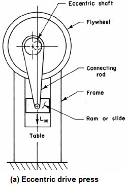
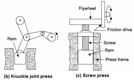
Figure 2: Types of mechanical presses
Eccentric mechanical presses (Figure-2a) utilize an eccentric crank to translate the rotary motion of the motor into a reciprocating linear motion of the press slide. The ram stroke is shorter than in a hammer or hydraulic press and hence the mechanical presses are best suited for low-profile forgings. Maximum load in these presses is attained when the ram is about 3 mm off the bottom dead centre position.
Knuckle joint presses and screw presses are also available (Figure-2 b & c). Because of the linkage design, very high forces can be applied in knuckle joint presses. Screw presses derive their energy from a flywheel. The forging load is transmitted through a vertical screw, and the ram comes to a stop when the flywheel energy is dissipated. If the dies do not close at the end of the cycle, the operation is repeated until the forging is completed.
4.2.2 Hydraulic presses
The operation of hydraulic presses is relatively simple and is based on the motion of a hydraulic piston guided in a cylinder. Hydraulic presses are essentially loadrestricted machines; i.e., their capability for carrying out a forming operation is limited mainly by the maximum available load. These presses are available in capacity of 50 to 1800 tones.
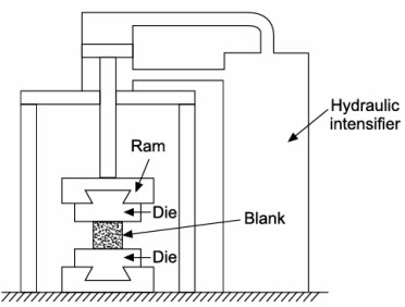
Figure 3: Hydraulic press
The following important features are offered by hydraulic presses:
(i) In direct-driven hydraulic presses, the maximum press load is available at any point during the entire ram stroke.
(ii) Since the maximum load is available during the entire stroke, relatively large energies are available for deformation. This is why the hydraulic press is ideally suited for forming operations requiring a nearly constant load over a long stroke.
(iii) Within the capacity of a hydraulic press, the maximum load can be limited to protect the tooling.
(iv) Within the limits of the machine, the ram speed can be varied continuously at will during an entire stroke cycle.
| Forging Machine | Speed range (m/s) | Speed-stroke behavior |
|---|---|---|
| Hydraulic press | 0.06-0.30 | 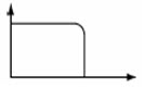 |
| Mechanical press | 0.06-1.5 | 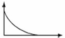 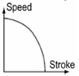 |
| Screw press | 0.6-1.2 | |
| Gravity drop hammer | 3.6-4.8 | |
| Power drop hammer | 3.0-9.0 | |
| Counterblow hammer (total speed) | 4.5-9.0 |
| Lecture 3 | Lecture 5 |