Using Angle Measurement
An angle can be an expression of a rotation. Every angle can be expressed in either a clockwise or a counter-clockwise rotation. The checking of angle can be done with various tools as per the requirement. Generally Plate Protractor, Bevel protractor, V-Block and sine bar are used.
Plate Protractor
The simplest angle-measuring device used in the machining industry is the plate protractor. The plate protractor is capable of measuring to within 1-degree. The flat back of the plate protractor makes it especially useful for layout work.
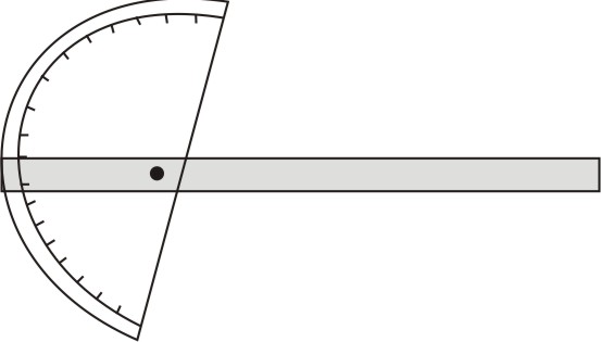
Figure 1: Bevel protractor
The bevel protractor picks up where the blade protractor leaves of. The bevel protractor is designed for precision measuring and layout of precision angles.
The bevel protractor consists of an adjustable blade with a graduated dial (main scale). The blade is usually 12 inches long. The main component of the bevel protractor is the (dial) main scale. The dial is graduated in degrees through a complete circle of 360o. The dial (main scale) is graduated into four 90-degree components i.e. the main scale is numbered to read from 0 to 90 degrees and then back from 90 degrees to 0.
As with other vernier measuring tools, the vernier scale of the bevel protractor allows the tool to divide each degree into smaller increments. The vernier scale is used for accurate angle adjustments and is accurate to 5 minutes or 1/12o. The vernier scale is divided into 24 equal graduations, 12 graduations on either side of the zero. Each graduation on the vernier scale is, therefore, one-twelfth of a degree.
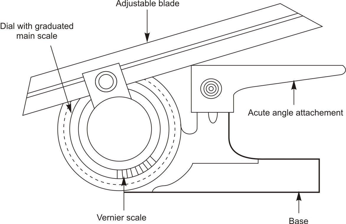
Figure 2: Measuring an angle with bevel protractor
The universal bevel protractor is capable of measuring obtuse angles as well as acute angles when accompanied with the correct attachments. Look at figure below to give you an idea as to the uses of the universal bevel protractor.
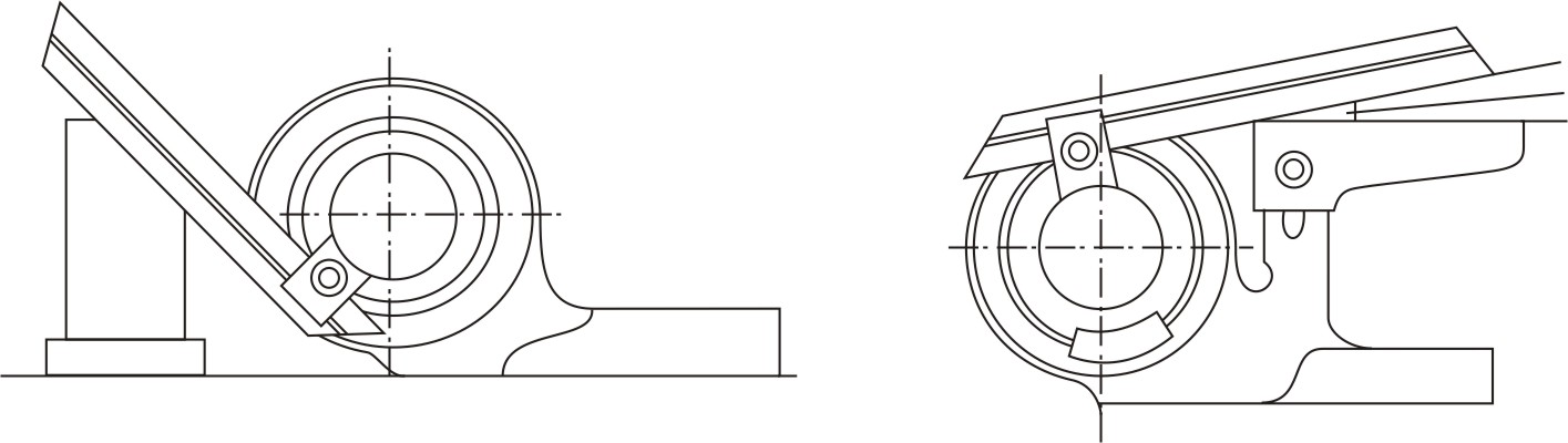
Figure 3: When reading from 90 degrees, make sure to note the positions where the angle and the supplement are formed
Using the bevel protractor
1. The blade of the protractor is held firmly in position and clamped.
2. Behind the protractor there should be arrangement of sufficient light to see that it is properly set.
3. Check that the protractor is correctly aligned with respect to the angle being measured.
4. To read the protractor, note where the zero on the vernier scale lines up with the degrees on the dial.
5. The degrees are read directly from the main scale while the minutes are read on the vernier scale.
6. Always read the vernier in the same direction that you read the dial.
Any angle can be measured with the vernier bevel protractor, but you have to be careful to note which part of a full circle are you measuring. For every position of the bevel protractor, four angles are formed.
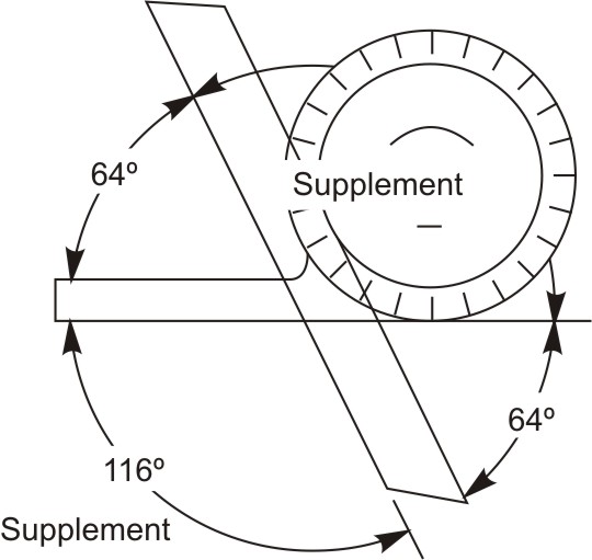
Figure 4: Set up of Sine bar
Two of the angles can be read directly on the main scale and the vernier scale while the other two are supplemental angles. Keep track of the obtuse and acute angles and try to read from zero whenever possible. There is no general rule for use, just keep in mind what you are adding to 90 degrees to make up the angle being measured.
Sine bar
The sine bar is used for accurately setting up work for machining or for inspection. Basically a sine bar is a bar of known length. When gauge blocks are placed under one end, the sine bar will tilt to a specific angle. Gage blocks are usually used for establishing the height. Rule for determining the height of the sine bar setting for a given angle: multiply the sine of the angle by the length of the sine bar. The sine of the angle is taken from the tables of trigonometric functions.
Limitation of the Sine bar is, when using a sine bar, the height setting is limited by the gauge block divisions available.
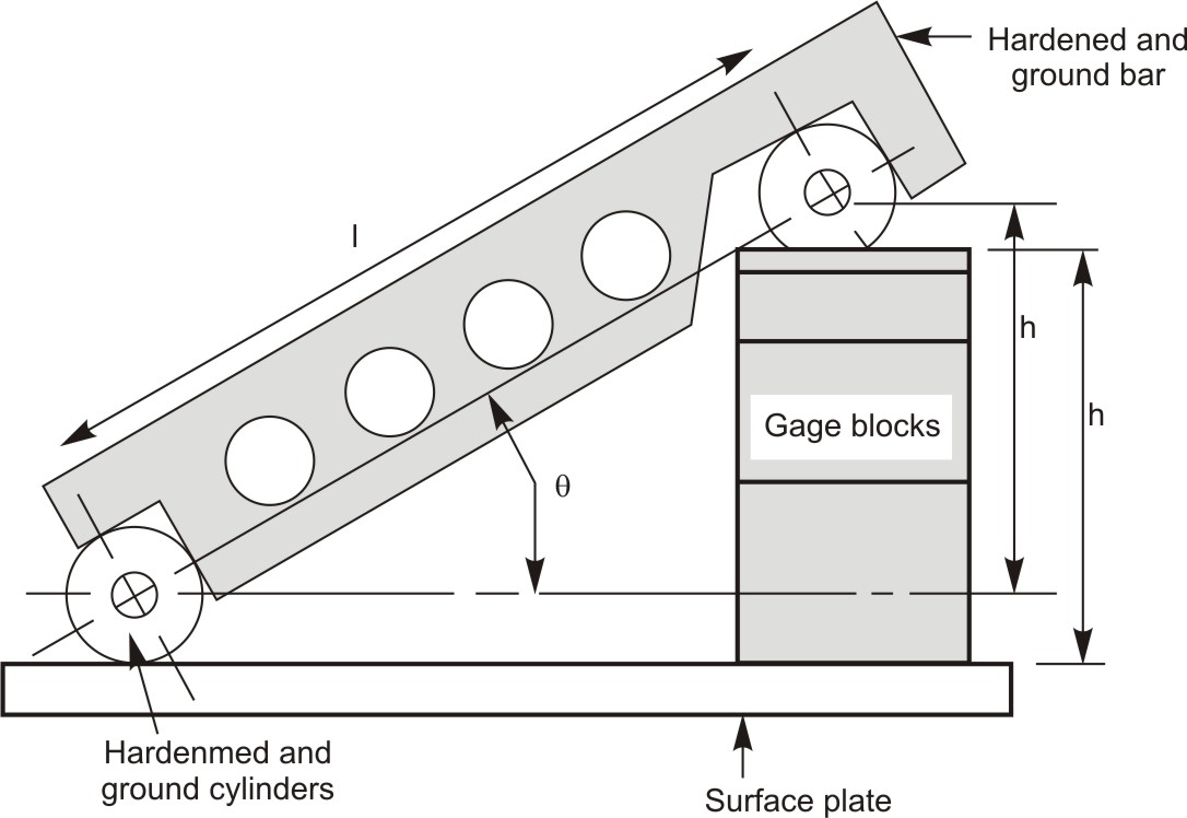
Figure 5: Set up of Sine bar
L=distance between centers of ground cylinders, generally 5inches or 10 inches
H=height of the gage blocks
?=Angle of the plate
?=sin(h/l)
Using Sine bar
1. Set the sine bar onto the granite surface plate.
2. Use the screws and knurled knobs to attach one workpiece to the sine bar in such a manner that the longest edge of the workpiece rests firmly on the surface plate and tighten the knurled knobs.
3. Ascertain that both rollers of the sine bar and the edge of the workpiece, along its full length, is in contact with the surface plate.
4. Calculate the height of the gage block stack that must be placed under one of the legs of the sine bar in order to make the top edge.
5. Check the parallelity with the test indicator mounted on a height gauge. If not parallel, change the height of the gauge block stack accordingly until parallelity is obtained.
6. Note that the hypotenuse, the length along the base of the sine bar, is five inches.
Degrees of accuracy of common measuring tools
| Measuring tool | Degree of accuracy | |
|---|---|---|
| Measuring tool | Degree of accuracy | |
| Steel Rule | 0.5 mm | 1/64 inch |
| Vernier caliper | 0.5 mm with main scale and 0.02 mm with vernier scale | 0.01 inch with main scale and 0.001 inch with vernier scale |
| Micrometer | 0.02 mm | 0.001 inch |
| Dial Indicator | 0.002 mm | 0.0001 inch |
| Tutorial 9 | Tutorial 11 |