Here the term operating conditions or cutting conditions refers to speed, feed and depth of cut motions required for metal cutting. As we discussed earlier, the definition of these operating conditions is different for different machine tools. For example, in a lathe, the term speed refers to the speed of job and in case of drilling machine it refers to the speed of the tool. Hence, here we first explain how the speed, feed and depth of cut motions are provided in a lathe. Refer Figure 2 for the three motions.
Selection of cutting conditions is made with respect to the type of machining operation. Cutting conditions should be decided in the order depth of cut - feed - cutting speed.
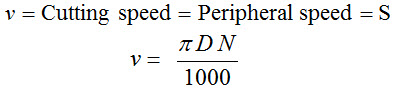
In a lathe, for turning operation, cutting speed is the peripheral speed of the workpiece past the cutting tool. For a workpiece, say a circular bar of diameter D rotating at N revolutions per minute (rpm), the peripheral speed is given by
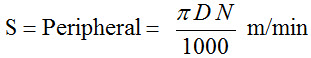
 (1)
(1)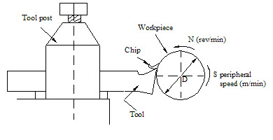
Figure 1: Cutting speed and peripheral speed of work piece in turning operation
In lathe operations, the term 'feed' implies the distance the tool advances for each revolution of the work. Feed in turning is generally expressed in mm per turning revolution (mm-tr-1). For example, if the feed is specified as 2 mm/revolution, it implies that the tool moves a distance of 2 mm for every revolution of the job. The direction of feed is shown in Figure 2.
Figure 2: Three motions in turning and direction of feed & depth of cut during turning operation
The depth of cut is the perpendicular distance measured from the machined surface to the uncut (or previous cut) surface of the workpiece. For turning operations, the depth of cut is expressed as:
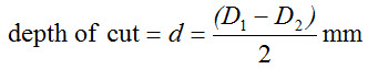 (2)
(2)D1 = original diameter of the workpiece in mm
D2 = final diameter of the workpiece in mm
In a turning operation if the depth of cut is 1 mm, then the diameter will be reduced by 2 mm. The values of speed, feed, depth of cut depends upon the type of workpiece material, tool material, type of surface finish required etc. In order to produce the desired dimension, the metal to be cut may be removed in two possible ways. Initially large amount of metal is removed to come closer to the desired final dimension without bothering about accuracy of dimension and surface finish. Only care to be taken is that the dimension is not reduced below the value. This type of metal cutting is called rough cutting or roughing operation. In roughing operations, depth of cut is made as large as possible (max depths are in the range of 6~10 mm) with respect to available machine tool, cutting tool strength, and other factors. Often, a series of roughing passes is required. Roughing operations must leave a thin layer of material (~0.5 mm on a side) required for the subsequent finishing operation.
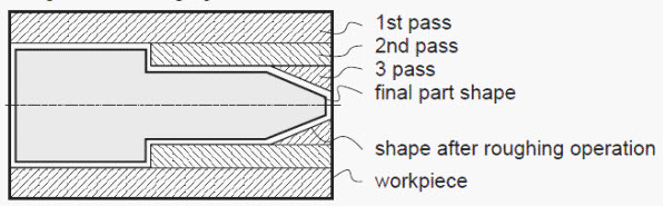
Figure 3: Example of selection of roughing passes in a turning operation
A finishing cut or finishing operation obtains the final dimension to the desired accuracy and surface finish. In finishing cut, very small amount of material is removed. Normally, only one finishing cut is made while there can be more than one roughing cuts depending upon the amount of material to be removed and permissible depth of cut. Roughing operation requires stronger tools for faster material removal, while for finishing cut new or freshly sharpened tool is used. In roughing, large feed and large depth of cut are used and in finishing, small depth of cut and low feeds are used.

Figure 4: Finishing pass in a turning operation
The material removal rate is the volume of material removed per unit time. Volume of material removed is a function of speed, feed and depth of cut. Higher are the values of these, more the material removal rate.
If D represents the original diameter of the workpiece in mm, d represents the depth of cut in mm, f represents the feed in mm/rev, then material removed per revolution is the volume of chip whose length is πD and whose cross section area is d x f. That is,
You can check the dimensional accuracy of these equations by substituting the units. For the Equation (4), (mm)(mm)(mm/rev)(rev/min) => mm3/min
and for Equation (5), (mm/m)(m/min)(mm)(mm) => mm3/min.
The time required to machine a component is called machining time. Machining time depends on size of the workpiece, amount of material to be removed and the operating conditions employed such as speed, feed and depth of cut.
Consider the speed of the job as N rpm, length of the job as Lj mm and f as feed in mm/rev. The product of feed and speed f x N is the feed rate in mm/min. It gives the distance the tool moves (f x N) in mm in one minute. Hence, for a distance Lj, the time required for one complete cut, t in minutes is given by
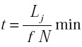 (6)
(6)Example: A 150 mm long 12 mm diameter stainless steel rod is to be reduced in diameter to 10 mm by turning on a lathe in one pass. The spindle rotates at 500 rpm, and the tool is traveling at an axial speed of 200 mm/min. Calculate the cutting speed, material removal rate and the time required for machining the steel rod.
Solution:
= 18.85 m/min.
depth of cut = d = (12 - 10)/2 = 1 mm
we get the feed f in mm/rev by dividing feed rate by spindle rpm.
That is
| Lecture 2 | Lecture 4 |