6.1 Introduction
The types of pattern used for a specific application depends primarily on the number of castings required, the moulding or casting process to be used, the size of the pattern and the casting tolerances that are required.
The common types of pattern are listed and described below:
(1) Solid or Single piece Pattern
(2) Split Pattern
(3) Match Plate Pattern
(4) Gated Pattern
(5) Cope and Drag Pattern
(6) Loose Piece Pattern
(7) Skeleton Pattern
(8) Sweep Pattern
(9) Left hand and Right hand Pattern
(10) Shell Pattern
(11) Segmental Pattern
(12) Follow Board Pattern
6.1.1 Solid or Single Piece Pattern
A single or solid piece pattern is made with out joints, loose pieces or partings. It has usually one board surface that serves as a parting surface in the mould. This type of pattern is used for a limited number of castings because most of the moulding operations like providing runners and risers, withdrawal of pattern etc. is done by hand. Soil temper glands of steam engines are made by solid or single piece pattern.
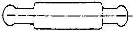

Fig. 6.1 Single, solid pattern
This type of pattern is used when the pattern if made is single piece will give rise to withdrawal difficulties from the mould. Split pattern consists of two pieces; one half of the pattern rests in the drag (lower part of the moulding box) and the other half in the cope (upper part of the moulding box).
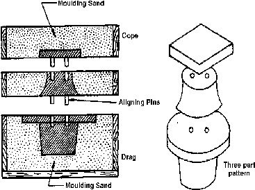
Fig. 6.2 Split patterns
The split patterns are commonly used for the casting of steam valve bodies, small pulleys, wheels and cylinders etc.
6.1.3 Match Plate Pattern
It is split pattern in which the cope and drag portions are mounted on opposite side of a plate, called match plate, conforming to the parting line. The pattern, as well as the associated gating and rising system, is usually made separately and then mounted on match plate, but can be cast integrally with the plate. The size of the match plate corresponds to the size of the flask used to make the final mould. Multiple patterns of small parts can be mounted on a single match plate can often be shared by the multiple patterns on the match plate. Interlocking features can be added to the cope and drag sides of the match plate to ensure accurate alignment of the cope and drag mould halves after removal of the pattern. Match plate pattern are used for moderate to high volume production of small and medium size castings with considerable dimensional accuracy.
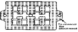
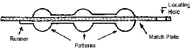
Fig. 6.3 Match plate pattern
Match plate pattern are used for moderate to high volume production of small and medium size castings with considerable dimensional accuracy.
6.1.4 Gated Pattern
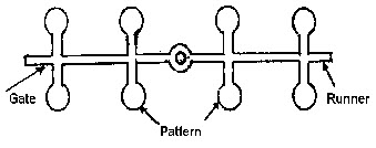
The gated pattern is used for mass production. For small castings, multi cavity moulds are prepared i.e. single moulds carry a number of cavities. Each pattern may be provided with a gate pattern with it examples are Vice Handle, Nuts and bolts etc.
(a)
(b)
Fig. 6.4 Gated patterns
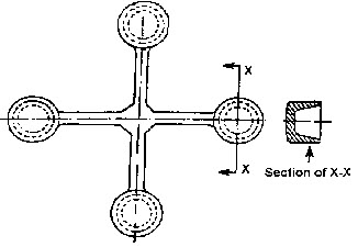
When large cavities are to be manufactured, the moulds are to be very heavy to handle. Separate pieces of pattern are made on a convenient joint line and mounted on boards with slots and holes provided with easier fittings. This arrangement helps the moulder to work on each piece separately. This ensures higher strength and durability.
6.1.6 Loose Piece Pattern
The loose piece pattern are needed when the casting is such that the pattern cannot be removed as one piece, even though the pattern is split and the parting line is made on more than one plane. In loose piece pattern the main pattern is removed first. Then the separate pieces which may have to be turned or moved before they can be taken out or removed.
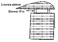
Fig. 6.5 Loose piece pattern
For large castings pattern would require a considerable amount of timber for fully solid pattern. In such cases the pattern is made of wooden frame and rib construction so that it will form an exterior or interior outline of casting. This framework is known as skeleton. Skeleton patterns are generally employed for symmetrical castings. Castings, which are generally made by making skeleton pattern, are valve bodies, pipe bends, water pipes and boxes.
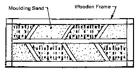
Fig. 6.6 Skeleton pattern
Uniform moulds and cores are shaped by sweep pattern. The sweep pattern consists of a wooden board having a shape corresponding to the shape of desired casting. It is arranged to rotate about a central axis. The sand is rammed and the board is made to rotate to get the desired shape mould. Sweep pattern is used for manufacturing of circular parts. This method is very economical since no actual pattern is needed and the pattern costs are kept at minimum by eliminating expensive pattern construction.
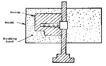
Fig. 6.7 Sweep pattern
Some patterns are required to be made in pairs and when their form is such that they can not be reversed and they have the centers of hubs etc, opposite and in line, they must be made left and right hand separately.
A pair of left and right hand patterns is required in legs of paddle type sewing machine, legs for wood turning lathe and legs of garden benches etc.
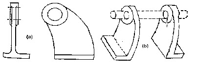
Fig. 6.8 Left and right pattern
Shell pattern is generally used for pipe work. This pattern is made of metal and its involves its mounting on a plate with a parting at the centre line and both the parts being pinned to each other. The shell pattern is a hollow construction like a shell. The outside shape is used as a pattern to make the mould while the inside is used as a core box for making cores.
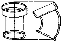
Fig. 6.9 Shell pattern
A segmental pattern resembles a sweep pattern in the sense that for getting the required shape, both employ a part of pattern and not the complete pattern. Both segmental and sweep patterns generate circular shapes. When a mould is to be made using this pattern, a vertical spindle is firmly fixed in the centre of lower moulding box. The mould bottom is rammed and swept level. The segmental pattern is fastened to the spindle. Moulding sand is rammed between the out side of the pattern and the flask and on the inside, except at the end of the pattern. After ramming one segment, next segment is rammed and so on until the entire perimeter of the mould is completed.
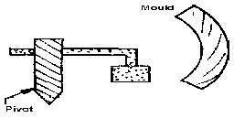
Fig. 6.10 Segmental pattern
Follow board is a wooden board and is used for supporting a pattern which is thin and which may give way and collapse under pressure when the sand above the pattern is being rammed. In some cases, the purpose of the follow board is not only to serve as a support to the thin pattern, but also forms an irregular parting line in the mould when the outlines of the pattern are irregular.
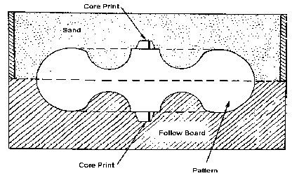
Fig. 6.11 Follow board pattern
Pattern is used to produce a casting of desired dimensions; it is not dimensionally identical to the casting. A number of allowances must be made on the pattern to ensure that the finished casting is dimensionally correct, to ensure that the pattern can be effectively removed from the mould. The following allowances are usually provided in a pattern.
6.2.1 Shrinkage Allowance
The various metals used for casting contract after solidification. It is the correction factor built into the pattern to compensate for the contraction of the metal casting as it solidifies and cools at room temperature. The pattern is intentionally made larger than the final desired casting dimensions to allow for solidification and cooling contraction of casting. The total contraction is volumetric, but usually expressed linearly.
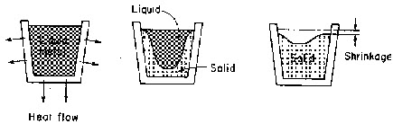
Fig. 6.12 Shrinkage Allowance
Table 6.1 Shows typical pattern shrinkage allowances for various casting materials
| Material being cast | Shrinkage allowance (mm/ meter) | Approximate shrinkage, % |
|---|---|---|
| Gray cast iron | 10.5 | 1.0 |
| Steel | 20 to 21 | 1.6 |
| Brass | 16 | 1.4 |
| Aluminium | 16 | 1.3 |
| Magnesium | 18 | 1.3 |
| Ductile cast iron | - | 0.8 |
Table 6.1 Typical pattern shrinkage allowances for various casting material
The contraction rule is a special scale that eliminates the need to compute the amount of the shrinkage allowance that must be provided on a given dimension. Each graduation on the shrink rule is proportionately longer than its conventional length. It is important to remember that pattern shrinkage allowances cannot be used to predict actual casting shrinkage. Other factors, such as casting shape, section thickness and mould rigidity significantly influence the actual change in dimensions as the casting solidifies and cools to room temperature.
6.2.2 Draft Allowance
Draft is taper allowed on the vertical faces of a pattern to permit its removal from the sand with out tearing the moulding walls. It may be represented in millimeters per meter on a side or degrees. The amount of taper varies with the type of patterns.
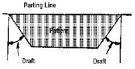
Fig. 6.13 Draft Allowance
The wooden patterns require more taper than metallic patterns because of greater frictional resistance of the wooden surfaces. The amount of draft also depends on the shape and size of casting, the moulding process used, the method of mould production and the condition of pattern. The draft angle of approximately 1.50 is often added to design dimensions. Interior surfaces usually require more draft than exterior surfaces.
6.2.3 Machining Allowance
It provides for sufficient excess metal on all cast surfaces that require machining. The required machine allowance depends on following factors:
(1) The size and shape of casting.
(2) The metal to be casted.
(3) Casting surface roughness and surface defect.
(4) Method of machining to be employed.
(5) The degree of finish required on the machined portion.
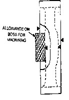
Fig. 6.14 Machining Allowance
Accurate patterns combined with automated moulding can often produce close tolerance casting with a minimum finish allowance that can reduce machining cost.
Table 6.2 shows suggested machining allowances.
| Pattern size (mm) | Allowance (mm) Bore | Allowance (mm) Surface | Allowance (mm) Cope side | Material |
|---|---|---|---|---|
| Upto152 | 3.2 | 2.4 | 4.8 | Cast iron |
| 152-305 | 3.2 | 3.2 | 6.4 | Cast iron |
| 305-510 | 4.8 | 4.0 | 6.4 | Cast iron |
| 510-915 | 6.4 | 4.8 | 6.4 | Cast iron |
| 915-1524 | 7.9 | 4.8 | 7.9 | Cast iron |
| Upto 152 | 3.2 | 3.2 | 6.4 | Cast steel |
| 152-305 | 6.4 | 4.8 | 6.4 | Cast steel |
| 305-510 | 6.4 | 6.4 | 7.9 | Cast steel |
| 510-915 | 7.1 | 6.4 | 9.6 | Cast steel |
| 915-1524 | 7.9 | 6.4 | 12.7 | Cast steel |
| Upto 7.6 | 1.6 | 1.6 | 1.6 | Non ferrous alloys |
| 76-152 | 2.4 | 1.6 | 2.4 | Non ferrous alloys |
| 152-305 | 2.4 | 1.6 | 3.2 | Non ferrous alloys |
| 305-510 | 3.2 | 2.4 | 3.2 | Non ferrous alloys |
| 510-915 | 3.2 | 3.2 | 4.0 | Non ferrous alloys |
| 915-1524 | 4.0 | 3.2 | 4.8 | Non ferrous alloys |
Table 6.2 Machining allowances
Certain cast shape, such as large flat plates and U shaped castings, sometimes distort when reproduced from straight or perfect patterns. This distortion is caused by the non-uniform contraction stresses during the solidification of irregularly shaped designs. Mechanically pressing or straighting normally corrects minor distortions. To eliminate this defect an opposite distortion is provided in the pattern, so that the effect is neutralized and the correct casting is obtained.
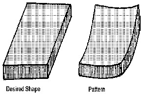
Fig. 6.15 Distortion Allowance
This allowance is provided in the pattern to compensate for the rapping of mould because the pattern is to be rapped before removing it from mould. As a result of this the size of the mould cavity increases a negative allowance is provided in the pattern to compensate the same. Small and medium size casting, this allowance can be neglected. But in large casting this allowance is considered by making the pattern slightly smaller than the casting.
Pattern colour coding is provided:
(1) To identify the type of metal to be casted.
(2) To show the part to be machined.
(3) To identify loose pieces, core prints.
(4) To identify the main part of the pattern from the remaining part.
(5) To show the part to be left un machined.
Table 6.3 shows the American colour coding.
| S.No. | Colour | Part |
|---|---|---|
| 1. | Red | Cast surface to be machined |
| 2. | Black | Cast surface to be left un machined |
| 3. | Yellow strip on black back ground | Core prints for un machined openings |
| 4. | Black strip on yellow background (diagonal) | Supports, stops offs |
| 5. | Yellow | Core prints seat |
| 6. | Red strips on yellow background | Loose pieces |
| 7. | Clear or no colour | Parting surfaces |
Table 6.3 Pattern colours
A good pattern may produce a sound casting but a bad pattern will always result in poor castings. Following factors should be considered while designing a pattern:
(1) Pattern should be accurate as regard to its dimensions and possess a very good surface finish.
(2) Proper allowance should be provided in pattern.
(3) Sharp corners of pattern should be avoided.
(4) Core prints provided for the pattern should be of optimum in size.
(5) Changes made in the shape should be gradual, uniform and smooth.
(6) Proper material for making the pattern should be selected.
(7) The wall thickness and section should be kept uniform.
(8) Pattern made for expected repeat orders should be preserved and stored properly.
Core is defined as that portion of the mould, which forms the hollow interior of the casting or hole through the casting. Core can also be defined as a body of dry sand generally prepared separately in a core box, baked in an oven and used to form a cavity of desired shape.
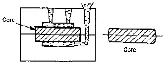
Fig. 6.16 Core
The core should have sufficient strength and hardness in both green and dry states so that it may be able to support its own weight. The main characteristics required for a good core are the following:
(1) It should not carry any such constituents, which will give rise to excessive gases on coming in contact with the molten metal.
(2) It must be sufficiently permeable to allow the gases formed to escape easily.
(3) It should be highly refractory to withstand the high heat of the molten metal.
(4) It should be hard and strong enough to bear its own weight and the force of molten metal.
Following are the commonly used cores:
6.6.1 Horizontal Core
The horizontal cores are used in foundry work frequently. It is usually in a cylindrical form laid in the mould horizontally. Depending upon the shape of the cross section of the hole to be made in the casting, it may have any shape of its cross section. If it has a uniform cross section such that its one half remains in the cope and the remaining half in the drag. Horizontal core is commonly used for making through holes.
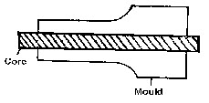
Fig. 6.17 Horizontal core
It is similar in shape to that of horizontal core. But placed in the mould with its axis vertical. The upper end of the core is placed in cope and the lower end is placed in the drag.
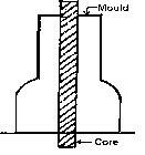
Fig. 6.18 Vertical core
When the casting has opening only on one side and only one core print is available on the pattern a balanced core is used. It is a horizontal core and used to produce a blind hole along a horizontal axis in the casting. It is supported only one end, the other end remaining free in the cavity of the mould.
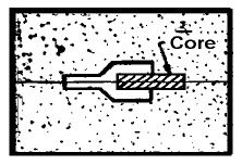
Fig. 6.19 Balance core
It is used, when a hole is to be obtained in the casting either above or below the parting line. Wire core is also used when it is not possible to place the pattern in the mould such that the recess can be cored directly. One side of the core remains flush with the inner surface of the mould and the core acts as a stop off. Back surface of the core has sufficient taper for easy location.
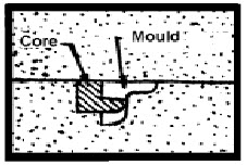
Fig. 6.20 Wire core
If the core hangs from the cope and does not have any support at the bottom in the drag, it is known as hanging core. A hanging core may be supported on a seat made on the parting surface in the drag.
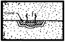
Fig. 6.21 Hanging core
Core prints are extra projections provided on the pattern. These form seats for cores in the mould. Core seats are provided to support all types of cores such as horizontal, vertical, balanced etc.
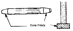
Fig. 6.22 Core prints
Core boxes are used for producing cores. Following are the main types of core boxes:
6.8.1 Half core box
Half portion of the core is made in the core box at one time. Number of such half cores made backed and passed together to make full cores.
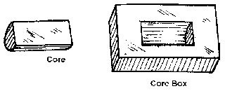
Fig. 6.23 Half core box
It is employed for making rectangular, square, or trapezoidal cores. Construction wise it is similar to half core box.
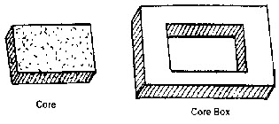
Fig. 6.24 Dump core box
These types of core boxes generally produce Pipe bends. Each box comprises of half of the pipe bend. The half of the pipe bends are rammed and baked and struck together to made full core.
6.8.4 Split Core Box
The two portions of split core box can be aligned and temporarily joined together with the help of dowels. A full core cavity is thus established. First the two halves are joined and the sand is rammed. The core box is then spilitted to remove the core.
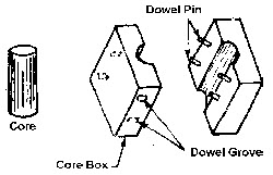
Fig. 6.25 Split core box
It is used to prepare two halves of a core which may be neither identical in size nor in shape. It can be achieved by inserting loose pieces in the core box whenever required.
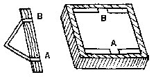
Fig. 6.26 Loose piece core box
It is used for producing irregular surfaces. The strickle board removes additional sand. It is made of wood.
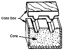
Fig. 6.27 Strickle core box