The mould is made by packing some readily formed aggregate material, such as moulding sand, around the pattern. When the pattern is withdrawn, its imprint provides the mould cavity, which is ultimately filled with metal to become the casting. A mould is required to get the desired shape and size of the metal casting. Sand is a good refractory material for most of the metals and is mostly used for moulding.
After going through this lesson, you will be able to understand:
1. Function of moulding in casting process.
2. Types of moulding sand and characteristics of sand used for moulding.
3. Moulding tools and procedure for making a mould.
Sand is the principle material used in foundry for making moulds. The principle ingredients of moulding sands are: silica sand grains, clay, moisture and special additives. Moulding sand possesses the following properties for making moulds: High fusion temperature and Good thermal stability. Moulding sands are classified into two categories viz.,
Natural moulding sand
Moulding sand available in nature is called natural moulding sand Natural moulding sands are taken from riverbeds or are dug from pits. Natural moulding sands are also obtained by crushing and milling soft yellow sandstone, rocks etc.
Artificial or synthetic moulding sand
The moulding sand prepared artificially, is known as artificial or synthetic moulding sand. Synthetic sands or artificial sands can be prepared in foundry shop by crushing sandstone and then washing and grading these to yield a sand grade of required shape and grain distribution. Synthetic sands are more expensive than natural sands.
Further moulding sands can be classified according to their use, composition into number of varieties. The desired strength and bonding property of these sands is developed by additive material. Also this addition allows greater flexibility in the properties such as permeability, dry strength of sand which can be easily designed as per requirement. The common moulding sands are described in sections below.
3.1.1 Green sand
The name 'green sand' implies 'damp' or un-dried sand, as the mould made from this sand is used immediately to pour the molten metal. It consists of silica sand with 18-30% clay and 4-8% water. Clay and water furnish the bond for green sand. Green sand retains the shape given to it and is collected from natural resources. The moulds using this sand are called as 'green sand moulds'. It has the advantage of maintaining moisture content for a long time.
3.1.2 Dry sand
Green sand that has been dried or baked after the mould preparation is called dry sand. Dry sand yields porosity absent castings, as there is no moisture. These are suitable for large size castings, say, heavier than 500 kg.
3.1.3 Loam sand
When clay and silica are mixed in equal proportions (50 - 50) with little or no special additives, it is called loam sand. It is used for loam moulding.
3.1.4 Parting sand
Parting sand is free from clay and is dry. Parting sand is used to keep the green sand from sticking to the pattern and to allow the sand on the parting surface of the flasks to separate without fitting tightly. This permits easy withdrawal of the pattern after ramming.
3.1.5 Core sand
Sand used for making cores is called core sand. Core sand is made of core oil, which is composed of linseed oil, resin, and other binding materials, is mixed with silica sand. Core sand should be stronger than the moulding sand.
Moulding sand must possess the following properties to produce good moulds and castings.
Refractoriness
Moulding sand must not fuse when it comes in contact with molten metal. As the mould should withstand the molten metal temperature while it is poured, the moulding sand should have sufficient refractoriness. Without sufficient refractoriness, the sand partially fuses with the molten metal giving rise to very rough sand-fused casting surface and causing rejection. For example, sand used for steel castings should have to withstand high pouring temperatures of above 1400oC.
Cohesiveness or strength
The ability of sand particles to stick together determines the cohesiveness or strength of sand. The moulding sand, when combined with a suitable binder, should develop adequate cohesion among its grains to be able to form and stay as mould. Moulding sand should be capable of withstanding the compressive and erosive force exerted by molten metal while filling mould cavity.
Collapsibility
After solidification of the molten metal, the casting is required to be removed from the mould. If the moulding sand is easily collapsible, free contraction of the metal as well as easy removal of the casting is possible. If the sand is not collapsible, it will strongly stick to the casting, becoming very hard to separate after the metal is solidified, resulting in high cost of finishing.
Adhesiveness
The sand particles stick to the mould box surfaces by the property called adhesiveness. This property helps the sand to retain the mould cavity and stay in the box.
Flowability
The capacity of moulding sand to flow to different corners and voids on pattern without much special effort is an important requirement of moulding sand. This property of the sand is known as flowability. This property is more significant in machine moulding.
Chemical resistivity
The sand used for moulding should be inert and should not react chemically with the metal/alloy being poured into it. Special care has to be taken while preparing moulding sand for casting reactive metals like magnesium and titanium alloys.
Permeability
The property of the sand to allow easy flow of gases and moisture through it is called permeability. Molten metals poured into mould cause evolution of gases due to their reaction with moulding elements such as binders, additives and water. Even a small amount of water added to moulding sand can evolve a lot of steam in few seconds while molten metal is filling in the mould.
Depending upon the raw material used for preparing the mould, moulds may be classified as:
Green sand mould
Moulds made up of green sand are known as green sand moulds. Green sand permits easy patching and finishing of moulds. These types of moulds are used for small and medium sized castings.
Dry sand mould
Dry sand moulds are made using green sand. Green sand is dried to remove all moisture of the green sand. The structure in the moulding boxes after drying becomes compact. Dry sand moulding is used for large castings.
Loam mould
The mould is first built up with bricks or large iron parts. These moulds are plastered with loam sand. Loam sand mould is dried very slowly and completely before it is ready for casting. Loam moulds are used for large castings.
Metal moulds
These moulds are made in metal and are used for die casting, permanent mould casting and centrifugal casting processes.
In a foundry shop, many different tools and equipment are used for making moulds and producing sound castings. Some of the important tools used for making sand moulds are shown in Fig. 4.1 and their functions are described below.
Shovel
It is used for mixing moulding sand and for filling moulding sand into the flask.
Riddle
It is used for removing foreign materials from the moulding sand.
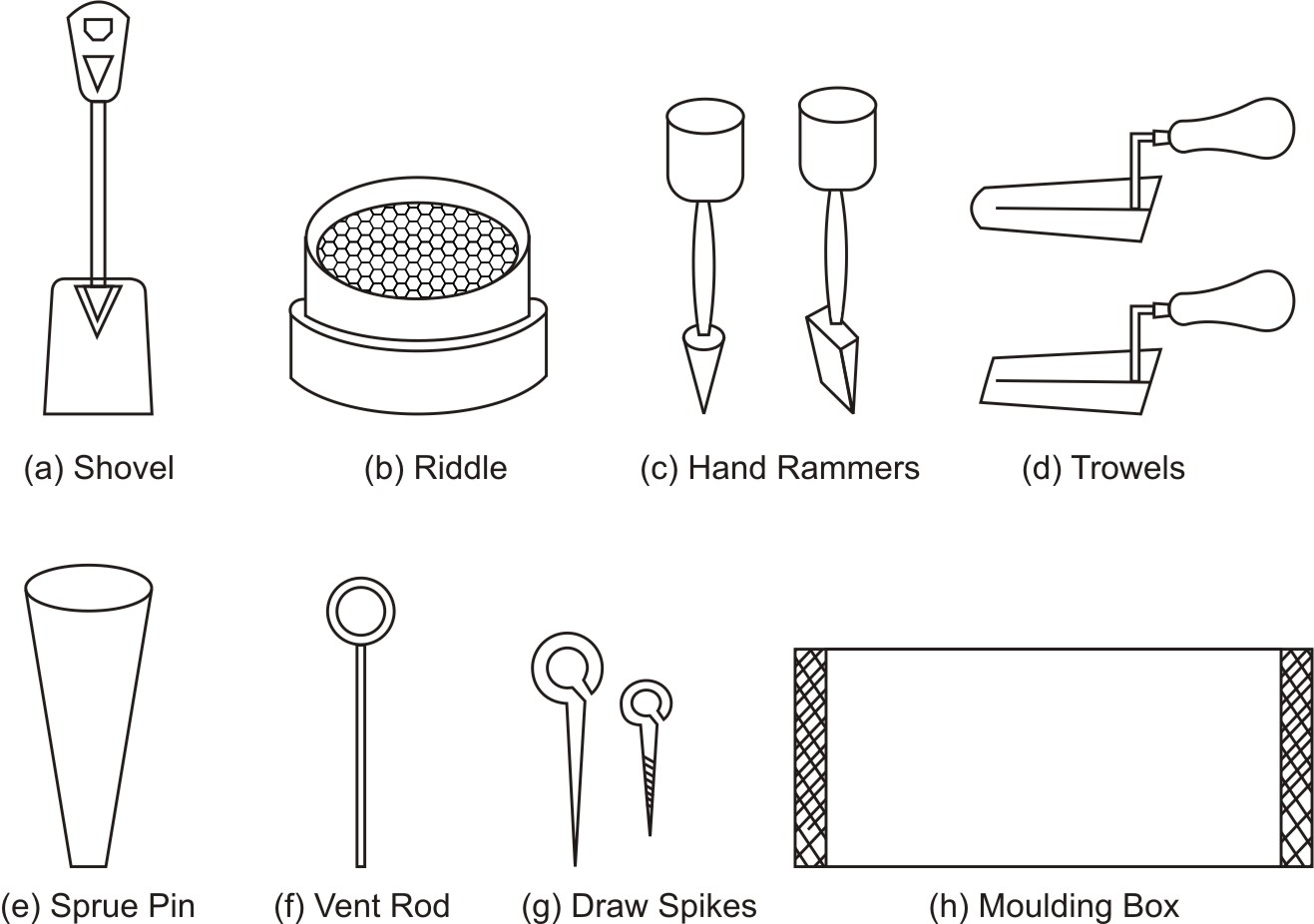
Fig. 3.1 Moulding tools used in foundry
Rammer
It is used for packing or ramming the sand into the mould.
Trowel
A trowel is used for smoothening the surfaces of the mould.
Sprue Pin
It is a conical wooden pin, which is used during making of mould, for making an opening to pour the molten material into the cavity.
Vent Rod
This is used for making small holes to permit gases to escape while the molten material is being poured.
Draw Spike
This is used for drawing patterns from the sand. This has a loop at one end for pulling up the pattern from the mould.
Moulding Boxes
These are also known as moulding flasks. Moulding boxes are rigid frames made of iron or wood to hold the sand. The purpose of a flask is to impart necessary rigidity and strength to the rammed sand. Complete process of moulding is done in the moulding boxes. They are generally made in two parts, which are assembled with each other by pins on either side of flasks. The top flask is called cope and the bottom flask is called drag. If the boxes are made in three sections then middle one is called as cheek.
Making a mould starts with placing the drag being used on a moulding board, and one half of the pattern is placed in the drag on the moulding board as shown in Fig. 3.2(a). Parting sand is spread over the pattern and the moulding sand is then pierced in to cover the pattern. The sand is pressed around the pattern with fingers and then the drag is completely filled with sand. For small moulds, the sand is tightly packed in the drag by a hand rammer. Once the ramming has been completed, the excess sand is leveled off with a straight bar called a strike rod and trowels. To facilitate the escape of gases when the metal is poured, small vent holes are made in the sand close to the pattern, with the help of vent rod.
The lower half of the mould, the drag, is then turned over, upside down. Before turning, a little parting sand is spread over the mould and another moulding board is placed on top. This board should be moved back and forth several times to guarantee an even bearing over the mould. After gently sloping over the drag, the moulding board is removed exposing the pattern. The surface of the sand is smoothened over with a trowel and covered with a fine coating of dry parting sand. Next, the cope is placed on the drag as shown in Fig. 3.2(b). The pins on either side hold it in proper position. The second half of the pattern is placed over the first half in proper location with the help of dowel pins. A sprue pin is placed about 20-30 mm away from the pattern at a suitable location.
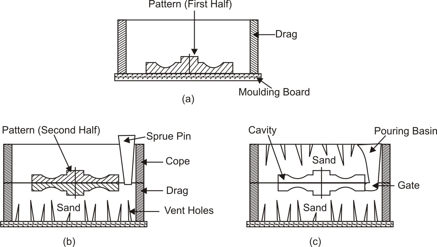
Fig. 3.2 Procedure for making a mould
After completing the above operations remove the pattern and the sprue pin. The sprue pin is first withdrawn and a funnel shaped opening is scooped out at the top so that there will be a large opening to pour the molten metal, see Fig. 3.2(c). The cope half of the flask is then carefully lifted off and placed on to one side. Before the pattern is withdrawn, the sand around the edge of the pattern is usually moisturized with a swab so that the edges of the sand hold firmly together when the pattern is withdrawn. To loosen the pattern from the rammed sand, a draw spike is driven into it and stroked lightly in all directions. The pattern can then be easily withdrawn by lifting the draw spike. In this manner both halves of pattern from cope and drag are removed.
Further, a small passage known as the gate is cut between the cavity made by the pattern and sprue opening. This passage is thinnest at the mould cavity, so that after the metal has been poured; the metal in the gate may be broken off close to the casting. The last step is to assemble the mould. The cope is carefully placed back in position above the drag and the mould is closed. The loose sand is blown off before closing the mould. The assembled mould is shown in Fig. 4.2(c). To balance for metal shrinkage during solidification, extra molten metal is stored in suitable location of the mould. A hollow is sometimes cut into the cope, which provides a supply of hot metal as the casting cools. This opening is called a riser.
To get holes or other internal cavities in castings, cores are used. A core may be defined as a sand shape or form, which makes the contour of a casting for which no provision has been made in the pattern. Core is like an obstruction placed and positioned in the mould shown in Fig. 3.3. Naturally, it does not permit the molten poured metal to fill up the space occupied by the core. In this way, a core produces hollow casting. Cores are surrounded on all sides by the molten metal and are subjected to much more severe thermal and mechanical conditions than mould walls. After the molten material is solidified, cores are ejected or broken, and the cavities are obtained in the castings.
Core of desired shape is produced separate from the sand mould. It is baked to make it strong and facilitate handling and setting into the mould. Cores are placed in the moulds in specially created cavities called core prints. Cores are generally made from sand, metal, plaster or ceramics.
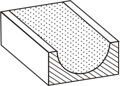
Fig. 3.3 Section of core box with ore in place
Core Making
Cores are made of clay-free silica sand, which is thoroughly mixed with suitable binders, water and other ingredients to produce a core mix. This core mix is packed into core box that contains a cavity of the desired shape.
The following operations are carried over to make core:
Core sand preparation
The core sand with additives is mixed homogeneously to obtain a uniform strength.
Core baking
Baking is carried out in order to remove moisture and to impart strength to the core. Proper baking is essential for a core to work satisfactorily. Under-baked cores release gases and may cause many defects. Over-baked cores may collapse too early and may break before the solidification of the metal.