Products made by sheet-metal forming processes are all around us. They include utensils, file cabinets, appliances, vehicle bodies etc. Compared to casting and forging, sheet-metal parts offer the advantages of lightweight and versatile shapes. Because of low cost and generally good strength and formability characteristics, low-carbon steel is the most commonly used sheet metal.
Material economy and the resultant reduction in weight and cost, high productivity, use of unskilled labor, and a high degree of possible precision have rendered Sheet metal press-work indispensable for many mass produced goods such as electronic appliances, steel furniture, utensils and vehicle bodies. The entire top of a car is finished to size from a single metal sheet. In sheet metal working, there is no need for further machining as required for castings or forging.
The importance of sheet metal can be best explained by an example. Component shown in Figure 6.1 can be manufactured by machining process or by sheet metal working. If sheet metal working is used, this reduces the material requirement and the manufacturing time to less than half.
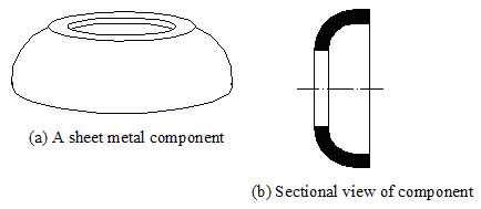
Figure 6.1 Components manufactured by sheet metal working
Sheet metal operations are usually carried by using punch and die. The mechanism of operation of punch and die is shown in Figure 6.2. Die is having the negative shape of the contour and punch has the positive contour of the shape to be produced. Sheet or plate to be shaped is kept over the die as shown in Figure 6.2(a). Then force is applied through the punch as shown in Figure 6.2(b). Small clearance is kept between punch and die for the thickness of sheet metal.
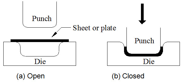
Figure 6.2 Operation of punch and die
Different operations can be performed by using a punch and a die on a sheet of metal. Some of these are described here.
6.3.1 Piercing and Punching
It is the operation of production of a hole in a sheet metal by the punch and die. The material punched out to form the hole constitutes the waste and the sheet with the hole is the required product.
In the case of punching, a cylindrical hole is produced, whereas in the case of piercing the hole produced may be of any other shape. Piercing operation is shown in Figure 6.3(a).
6.3.2 Blanking
Blanking is the operation of cutting a piece of required shape from a sheet using a punch and a die. The metal punched out is the required product in blanking and is called blank. Blanking operation is shown in Figure 6.3(b).
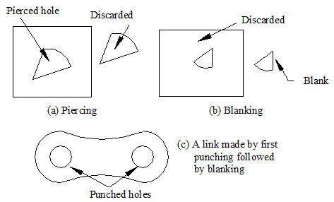
Figure 6.3 Piercing and blanking operations
It is the operation of removal of metal of the desired shape from the edge of the plate. Notching is shown in Figure 6.4.
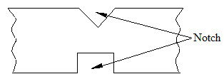
Figure 6.4 Notching
Beading is the forming of the rolled edge by bending the edge of sheet metal. This is shown in Figure 6.5. It gives strength and stiffness to the edge and sharp edges that might injure the users of the part are avoided.
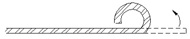
Figure 6.5 Beading
Flanging is the process of bending the edges of sheet metals at 90 degrees. Flanging is done to increase the stiffness or to join two sheet metal parts. This is as shown in Figure 6.6.
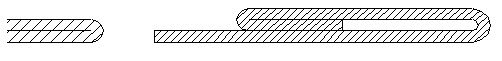
Figure 6.6 Flanging
Hemming refers to the process of folding over the edge of a piece of sheet metal and pressing it flat. This stiffens the sheet and creates safer, non-jogged edge. This is shown in Figure 6.7.
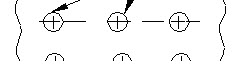
Figure 6.7 Hemming single and double hemming
For joining two sheets at the edges, without use of fasteners, welding or other joining processes, seaming operation is used. Seaming is similar to hemming operation and is shown in Figure 6.8. One or both sheets are flanged before seaming. An example of seaming operation is the joining of top cover with the cylindrical body of beverage cans and food containers.

Figure 6.8 Seaming
Perforating is the operation of production of a number of evenly spaced holes in a regular pattern on a sheet metal. It is shown in Figure 6.9.
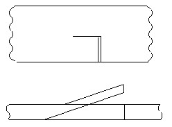
Figure 6.9 Perforating
Slitting is the operation of cutting a sheet metal along a straight line along the length. Slitting is shown in Figure 6.10.

Figure 6.10 Slitting
Lancing is the operation of cutting a sheet of metal through part of its length and bending the cut portion. Lancing is shown in Figure 6.11.
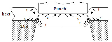
Figure 6.11 Lancing
The process of blanking is shown in Figure 6.12. The sheet is placed between the punch and the die. The punch diameter (size) is the size of the blank required and the die is made slightly bigger in size. The sheet is firmly held down and punch is forced into the sheet. The compressive stresses acting in the metal give rise to the strain distribution, as shown in Figure 6.12.
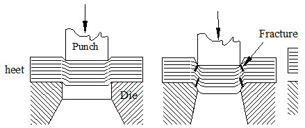
Figure 6.12 Mechanism of blanking
The dragging down of the punch into the sheet produces tensile stresses at the punch edges. Due to the diagonal pinching of the metal between the approaching faces of punch and die, the metal in between is subjected to compressive stresses, leading to relative shear and fracture of metal. As you see in Figure 6.12, the material is subjected to both compressive and tensile stresses. The different stages of shear of metal plate involved in blanking are shown in Figure 6.13.
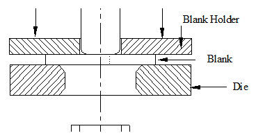
Figure 6.13 Different stages in blanking
In the first stage, the punch presses the sheet and the latter is subjected to elastic deformation, as shown in Figure 6.13(a). With subsequent penetration of the punch, the plastic deformation commences and proceeds. With more and more penetration, the surface tensile stresses in the sheet metal go on increasing and at one stage the ultimate tensile strength of the surface material is exceeded, giving rise to fractures at the punch and die edges, as shown in Figure 6.13(b). In the third stage, the cracks propagate with further increase in punch stroke as shown in Figure 6.13(c), and when the area of cross-section reduces sufficiently, it fractures suddenly causing a tensile cleavage fracture separating the blank from the sheet.
The process of shaping a flat or a hollow blank into a three-dimensional hollow component without any appreciable change in sheet thickness is called drawing. If the depth to diameter ratio is more than 0.4, then it is called deep drawing. The drawing process is shown in Figure 6.14. During this process, a punch forces the blank to flow through a die, so that it assumes a cylindrical, box or cup shape. Considerable compressive stresses appear in the flange portion of the blank being drawn, and this causes wrinkling if the blank thickness is small. To prevent wrinkling a blank holder is used which holds the blank firmly until it is completely drawn.
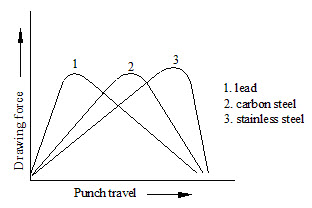
Figure 6.14 Drawing operation
Pulling the blank into the die cavity induces compressive stress, which tend to cause the flange to wrinkle during drawing. You can demonstrate wrinkling by trying to force a circular piece of paper into a round cavity such as a drinking glass. Wrinkling can be reduced or eliminated if a blank holder is used. The blank holder presses the sheet down under a certain force and prevents wrinkling.
In a single stage drawing operation, a cup may be obtained of a diameter from 1.8 to 2 times less than that of the initial flat blank. Upon more deformation, the drawing force required increases to such an extent that the metal is ruptured. A further reduction in cup diameter is possible only by subsequent forming operation called redrawing.
6.5.1 Drawing or Shearing Force
The total force required for drawing is the addition of ideal drawing force plus frictional forces plus bending and restraightening forces acting at the die radius region. The drawing force does not remain constant throughout the stroke of the process. At the beginning of the stroke it increases rapidly and reaches a maximum due to strain hardening of the material. Thereafter, it starts decreasing. The drawing force variation is shown in Figure 6.15 for three different types of materials.
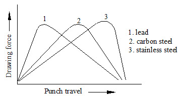
Figure 6.15 Force variation during deep drawing
The forces developed in a drawing or shearing operation depend upon the die clearance i.e. the gap between punch and die, the shear strength of the material to be drawn or cut and the sheet thickness.
The term coining refers to the cold squeezing of metal while all of the surfaces are confined within a set of dies. The process is used for the production of coins, medals etc. The metal is coined in a completely closed die cavity. The pressures required can be as high as 5-6 times the strength of the material in order to produce fine details. Figure 6.16 illustrates the coining process.
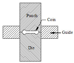
Figure 6.16 Coining process
The operation is performed in dies that confined metal and restrict its flow in a lateral direction. Metals having good malleability are suitable for coining. The metal blank of proper size is placed within the punch and the die and tremendous pressure is applied on the blank from both ends. Under sever compressive load, the metal flows in the cold state and fills up the cavity of the punch and die. The component thus produced gets a sharp impression on its surfaces, corresponding to the engravings on the punch and the die.
Several coining operations may be required in order to produce fine details on some parts. Lubricants cannot be used in coining, since they can be entrapped in the die cavity and, being incompressible, prevent the full reproduction of die-surface details on the metal.
Embossing is the operation of producing raised or depressed impression of figures, letters or designs on sheet metal parts. The major use of embossing process in the production of nameplates, identification tags and aesthetic designs on thin sheet metal or foil. Embossing process is shown in Figure 6.17.
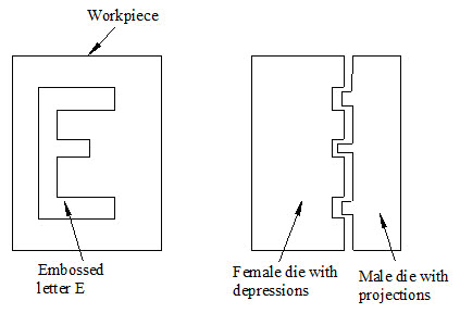
Figure 6.17 Embossing process
The punch, or the die, or both of them may have the engravings of the shape to be produced on the workpiece. The work piece material is stretched over a male die and caused to conform to the male die surface by a mating female surface die. The finished product will have depressed detail on one side and a raised detail on the other. Embossing is more of a drawing or stretching operation and does not require the high pressures necessary for coining. Embossing is a cold working process.
The process of wire drawing is shown in Figure 6.18.
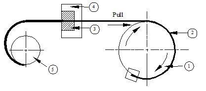
Figure 6.18 Wire drawing process
Wire drawing involves pulling metal through a die. A tensile force is applied to the metal on the exit side of the die. Most of the plastic flow of the metal is caused by radial compression force, which arises from the reaction of the metal area within the die. Depending on the diameter of the final product obtained, the process may be termed as bar, rod, or wire drawing. For wire drawing, material must have a good ductility. Sometimes, the material is annealed to improve the ductility before it is subjected to wire drawing process. The material, which is subjected to wire drawing process, must be clean and free from scale, dust etc. the presence of which can severely affect the die. The pressures acting at the interface of the die and the metal being very high, the lubrication of the die is a serious problem.
The important feature of the wire drawing operation is that the material can be drawn down to very small diameters and to exact sizes. But, for obtaining significant changes in the size multiple passes are required. The surface finish obtained in cold drawing is excellent. The drawing speeds of modern wire drawing equipment exceed 1500 m/min.
Some of the applications of this process are manufacture of fine wires for electrical and transformer industry, filaments and lead in wires for lamps, etc.
Example 6.1 A square duct required for an air-conditioning system is to be made from Aluminum sheet metal. The duct is shown in Figure 6.19 and shaded portions in the figure indicate places where sheet metal work has to done. Identify the different sheet metal operations involved in manufacturing the duct. Illustrate the sequence of these operations
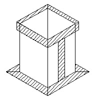
Figure 6.19 The duct to be manufactured
The duct is made from sheet metal by performing the following operations:
1. Bending or folding to get the square shape,
2. Seaming at the edges of the sheet after folding to join the two edges,
3. Hemming at the top edge, and
4. Flanging at the bottom edge.
The bottom edge is flanged to facilitate joining of two ducts or fixing the duct to the wall bracket. The stages of manufacturing the duct are illustrated in Figure 6.20.
The stages of manufacturing the duct are explained below:
1. First, the raw material (Al sheet) is marked, that is, lines at which sheet is to be bent or folded, to form the square duct, are marked. See Figure 6.20(a).
2. Next, the sheet is folded over a die and seaming is done to join the two edges of the sheet, as shown in Figure 6.20(b).
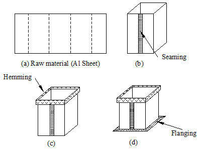
Figure 6.20 Different stages in producing ductwork
3. Next, hemming is done at the top edge of the square duct formed in previous step. It is shown in Figure 6.20(c).
4. Finally, the lower edge of the duct is flanged (folded) to produce the final duct. This is shown in Figure 6.20(d).
| Lecture 5 |