A majority of components have one or more cylindrical holes in them. Holes are needed for most common fasteners such as bolts and screws. Drilling is a process of producing round holes in a solid material or enlarging existing holes with the use of multi-tooth cutting tools called drills or drill bits. Various cutting tools are available for drilling, but the most common is the twist drill.
The machine tool used for drilling is the drilling machine, which is also called drill press. Schematics of two common types of drilling machines are shown in Figure 1; the drill press in Figure 1(a) and a radial drilling machine in Figure 1(b).

Figure 1: Two types of common drilling machines
The workpiece is placed on the adjustable table, and is clamped firmly both for safety and accuracy to overcome the high drilling torque. The cutting tool, twist drill, is fastened to the end of the vertical spindle, which is rotated at the desired speed. In drilling the workpiece remains stationary and tool is rotated as well as fed into the workpiece. The rotating drill is fed against a stationary workpiece either by hand feed or by power feed. The vertical motion of the drill is the feed in drilling operations.
Generally, the holes produced by drilling are large than the drill diameter, this you can notice by observing that a drill can be removed easily from the hole it has just produced. The amount of oversize will depend on the quality of drill, the equipment used, and the practices employed. The surface finish of the hole produced by drilling is also poor. For these reasons, the drilled holes are subjected to other operations for better surface finish and dimensional accuracy, such as boring and reaming.
The tool employed to drill holes is called drill which has two symmetrical opposite cutting edges, each removing part of the material in the form of chip. A typical drill and its important features are shown in Figure 2. A drill consists of the body, point, neck and shank. The shank is for holding or fixing the drill in the drilling machine, it is either taper or straight. The two cutting edges are at the point forming the point
angle and chisel edge angle. The metal cutting takes place at the drill tip by the two cutting edges. Drills usually have large length to diameter ratio. The chips that are produced within the workpiece have to move in the direction opposite to the axial movement of the drill and the cutting fluid has to reach the cutting edges at the end of drill. Hence, chip disposal and the effectiveness of cutting fluids are
significant problems in drilling. Generally, two spiral grooves or helical flutes with a specific helix angle run the length of the drill body. The chips produced are guided upward through these flutes and the coolant reaches the cutting edges through them. In some drills these flutes are straight, thus, drill are classified as twist or flat drills.
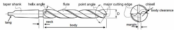
Figure 2: Geometry of the twist drills
The cutting speed v in drilling is the peripheral speed of the drill. The cutting speed that should be used in drilling depends on number of factors properties of material being drilled, drill material, drill diameter, rate of feed, coolant use.
The feed f is the movement of the drill along its axis. It is usually specified in millimeters per revolution of the drill.

Figure 3: Basics of drilling operation

The choice of operating conditions in drilling operations becomes more critical with an increase in the hole depth. As the depth of hole increases (i) the chip ejection becomes more difficult, and (ii) fresh cutting fluid is not able to reach to the cutting zone. These factors lead to overheating of the drill and shorten its life. Hence, for machining lengthy holes reduced feed rates are used. For machining holes of very large length a special type of drilling process known as gun drilling is used. By using this process, it is possible to machine the holes having length greater than 300 times the diameter.
The cutting speed v decides the speed of rotation of the drill N based on the diameter of the drill D. The cutting speed is given by
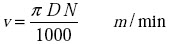 (1)
(1)The material removal rate (MRR) in drilling is the volume of material removed by drill per unit time. For a drill with a diameter D, the cross-sectional area of the drilled hole is iD2/4. The material removal rate is the product of cross-sectional area of the drilled hole, feed rate f (in mm/rev) and the rotational speed N of the drill. That is,
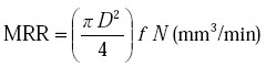 (2)
(2)
The machining time for drilling a hole depends upon the length of the hole to be drilled L, rpm of the drill N and feed f. If t is time required to drill a hole, then
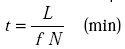 (3)
(3)In order to drill a through hole, the drill must pass through the thickness of workpiece. This means the travel of the drill is more than the length of hole. Thus, in actual practice, for the hole length Lj we add length of approach (or approach) L1 and length of recess (or over travel) L2 for the calculation of time t. These are illustrated in Figure 4.
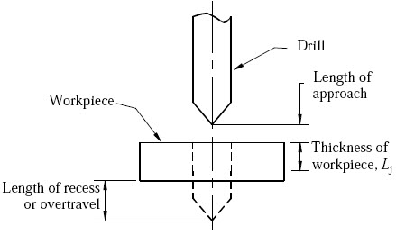
Figure 4: Length of approach and length of recess
Drilling is used to drill a round blind or through hole in a solid material. If the hole is larger than ~30 mm, its a good idea to drill a smaller pilot hole before core drilling the final one. For holes larger than ~50 mm, three-step drilling is recommended;
Core drilling is used to increase the diameter of an existing hole;
Step drilling is used to drill a stepped (multi-diameter) hole in a solid material;
Counter boring provides a stepped hole again but with flat and perpendicular relative to hole axis face. The hole is used to seat internal hexagonal bolt heads;
Countersinking is similar to counter boring, except that the step is conical for flat head screws;
Reaming provides a better tolerance and surface finish to an initially drilled hole. Reaming slightly increases the hole diameter. The tool is called reamer;
Center drilling is used to drill a starting hole to precisely define the location for subsequent drilling. The tool is called center drill. A center drill has a thick shaft and very short flutes. It is therefore very stiff and will not walk as the hole is getting started;
Gun drilling is a specific operation to drill holes with very large length-to-diameter ratio up to L/D ~300. There are several modifications of this operation but in all cases cutting fluid is delivered directly to the cutting zone internally through the drill to cool and lubricate the cutting edges, and to remove the chips;

Figure 5: Various drilling and reaming operations
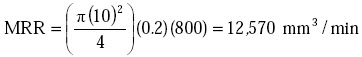
Example 1: A hole is being drilled in block of magnesium alloy with a 10 mm drill at a feed of 0.2 mm/rev. The spindle is running at 800 rpm. Calculate the MRR.
Solution:
Given data: D = 10 mm, f = 0.2 mm/rev, N = 800 rpm
Substituting the values in Equation (2), we get
Example 2: Calculate the time required to drill a 25 mm diameter hole in a workpiece having thickness of 60 mm to the complete depth. The cutting speed is 14 m/min. and feed is 0.3 mm/rev. Assume length of approach and over travel as 5 mm.
Solution:
Given data: D = 20 mm, Lj = 60 mm, v = 14 m/min, f = 0.3 mm/ rev. with usual notations.
Substituting the data in the Equation (1), we calculate the drill rotational speed, that is
or
N = 178 rpm.
= 1.21 minute.
| Lecture 6 |