A family of shaping operations through which undesired excess material is removed from a starting work piece so the remaining work piece become closer to the desired shape. Following are the categories of material removal processes:
Machining - material removal by a sharp cutting tool, e.g., turning, milling, drilling
Abrasive processes - material removal by hard, abrasive particles, e.g., grinding
Nontraditional processes - various energy forms other than sharp cutting tool to remove material, e.g., electrochemical processes, chemical machining.
Machining is the process of removing excess material from a work piece by shearing in the form of chips by cutting tools. If the work piece is metal, the process is often called metal cutting. Majority of manufactured products require machining at some stage in their production, ranging from relatively rough or non-precision work, such as cleanup of castings or forgings, to high-precision work and high-quality finishes. Thus machining undoubtedly is the most important of the basic manufacturing processes.
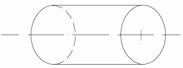 | 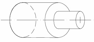 | 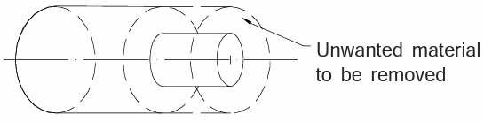 |
| Initial over size work piece | Final shape sought | Excess material to be removed from the initial work piece in order to achieve final shape / product |
The essential basic requirements for machining work are schematically illustrated in Figure below. The blank (work piece) and the cutting tool are properly mounted (in fixtures/chuck/jaw) and moved in a powerful device called machine tool (lathe / drilling / milling machines) enabling gradual removal of layer of material from the work surface resulting in its desired dimensions and surface finish. Additionally some environment called cutting fluid is generally used to ease machining by cooling and lubrication.

Figure 2: Requirements for machining
a. Other processes such as casting, forging, and bar drawing create the general shape
b. Machining provides the final shape, dimensions, finish, and special geometric details
c. A variety of materials can be shaped using machining
d. 'Repeatable' regular geometries with close tolerance (<0.025μm) and smooth surface finish (0.4μm) can be obtained.
e. Machining process is expensive as it involves waste and more time. Machine Tools produce geometrical surfaces like flat, cylindrical or any contour on the preformed blanks by machining work with the help of cutting tools.
The physical functions of a machine tool in machining are:
1. Firmly holding the blank and the tool
2. Transmit motions to the tool and the blank
3. Provide power to the tool-work pair for the machining action.
4. Control of the machining parameters, i.e., speed, feed and depth of cut.
The process of metal cutting is complex because it has such a wide variety of inputs.
The variables are:
1. The machine tool selected to perform the process
2. The cutting tool selected (geometry and material)
3. The properties and parameters of the workpiece
4. The cutting parameters selected (speed, feed, depth of cut)
5. The workpiece holding devices or fixtures or jigs
There are seven basic material removal processes (see Figure below): turning, milling, drilling, sawing, broaching, shaping (planing), and grinding (also called abrasive machining).
 | 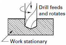 | 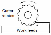 |
| Turning | Drilling | Milling |
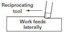 | 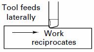 | 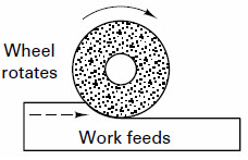 |
| Shaping | Planing | Grinding |
 | 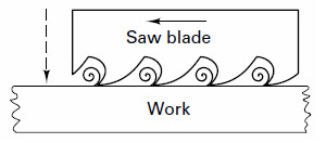 | |
| Broaching | Cutting | |
Lathe is known as mother of machine tools. The lathe machine tool is used for producing components that have one or more cylindrical surface, which may be internal or external. With special attachments, it can also be used for producing flat surfaces, other types of surfaces, cutting threads, cutting grooves and holes. Figure below shows some typical products that are made using a lathe.
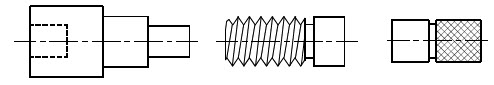
Figure 4: Some typical components produced on lathe
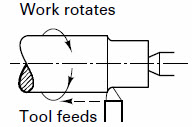
Typically, to perform metal cutting operations on a lathe, the work piece is held firmly and rotated (turned) and the material is removed from the work piece by feeding the cutting tool against the rotating work piece. This is the turning operation.

Figure 5: Pictorial representation of lather

Figure 6: Schematic representation of general purpose lathe
Typical products made from lathe include parts as small as miniature screws for eyeglass-frame hinges and as large as rolls for rolling mills, gun barrels.
1.3.1 Bed - The bed is the foundation of the working parts of the lathe to another. Beds have a large mass and are built usually from gray cast iron to resist deflection and absorb vibrations generated during the process of cutting.
1.3.2 Guideways - Guideways are formed on the upper surface of bed and run the full length of the bed. It provide the means for holding the tailstock and carriage, which slide along the ways, in alignment with the permanently attached headstock. Guideways are hardened to make them wear resistant and are machined accurately to give dimensional accuracy.
1.3.3 Headstock - Headstock is located on the left end of the lathe bed. It contains the main spindle and the gearing mechanism for obtaining various spindle speeds and for transmitting power to the feeding and threading mechanism. The center of the spindle is hollow so that long bars may be put through it for machining.
1.3.4 Spindle - Spindle is mounted on bearings in the headstock and is hardened and specially ground to fit different lathe holding devices. It has a hole through its entire length to accommodate long work pieces. Chucks, drive plates, and faceplates may be screwed onto the spindle or clamped onto the spindle nose.
1.3.5 Tailstock - The tailstock is mounted on the guideways (opposite end of the lathe from the headstock) and is designed to be adjusted laterally by adjusting screws. It supports one end of the long work pieces when machining between centers, and holds various forms of cutting tools, such as drills, reamers, and taps.
It has a quill, into which the dead centre, drills and reamers can be fixed. The quill can move in and out with the help of hand wheel.
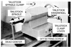
Figure 7: Enlarged pictorial view of lathe tailstock
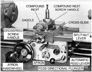
Figure 8: Enlarged pictorial view of lathe carriage assembly
1.3.6 Carriage assembly - The main function of the carriage is to hold the cutting tool and move it to give longitudinal and/or cross feed. The carriage includes the apron, saddle, compound rest, cross slide, tool post, and the cutting tool. This provides the motion along the Z axis.
Figure 8: Enlarged pictorial view of lathe carriage assembly
The saddle carries the cross slide and the compound rest.
The cross slide is mounted on the dovetail ways on the top of the saddle and moves radially back and forth (X axis) at 90o to the axis of the lathe by the cross slide lead screw. Thus controlling the radial position of the cutting tool.
The compound rest is mounted on the cross slide and has circular base graduated in degrees. It can be swiveled and clamped at any angle in a horizontal plane. It is used for obtaining angular cuts and short tapers. The cutting tool and tool holder are secured in the tool post, which is mounted directly to the compound rest.
The apron attached to the front of the carriage contains the gears and feed clutches which transmit motion from the feed rod or lead screw to the carriage and cross slide. It is equipped with mechanisms for both manual and mechanized movements.
A split nut in the apron is used to engage the lead screw with the carriage.
A feed reversing lever, located on the carriage, is used to cause the carriage and the cross slide to reverse the direction of travel.
1.3.7 Feed rod - The feed rod is powered by a set of gears from the headstock. It rotates during operation of the lathe and provides mechanized movement to the carriage or the cross-slide by means of gears, a friction clutch, and a keyway along the length of the feed rod.
1.3.8 Lead screw - The lead screw is also powered by the gears from the headstock and is used for providing specific accurate mechanized movement to the carriage for cutting threads on the workpiece. The lead screw has a definite pitch. Similarly, a lathe not meant for thread cutting will not have a lead screw.
The size of a lathe is specified by two or three dimensions, i.e. maximum diameter of the workpiece that can be machined (this is called swing), the maximum distance between tailstock and headstock centres, and the length of the bed. For example, a lathe is specified as having swing of 300 mm means the maximum diameter of the job that can be machined (swung) on that lathe is 300 mm.

Figure 9: Specification of lathe size
| Lecture 2 |